leds respond to light, will generate noise from any varying light i.e. flouresent or monitor, so do diodes and transistors in glass packages
Yes, they respond to light, but the response is shunted by their own very low dynamic resistance because they are directly biased . Don't worry.
leds respond to light, will generate noise from any varying light i.e. flouresent or monitor, so do diodes and transistors in glass packages
Only reverse biased. I think I posted some measurements about this a few years ago; stuck a fluorescent light right next to a lit LED and saw absolutely no effect.
edit: Just saw Wavebourn's post. What he said.
Hi Capt Grogg,
I think you must be referring to reverse biased glass diodes only. Those get a case of the nasties when exposed to florescent light. Too bad because we see glass signal diodes everywhere (1N4148, 1N914) in reverse biased applications.
I have not seen this effect from any forward biased LEDs, and you don't really want to reverse bias LEDs. Some have a low reverse breakdown voltage. I have not seen damage from this, but what's the point of doing it?
Anatoliy's explanation is good enough for me. Never thought about this case to be honest with you.
Hi Syn08,
Very good of you do do this, thank you. I'm feeling better about my way of building a current source already! Red LED (cheap) and a BJT.
Now, if you are going to test some J-Fets for this, may I suggest a couple that might be popular as well? In no way do I want to overload you.
J202 - Along with J201. Same family but higher IDSS for the J202.
2N5484 - Recommended to me.
2SK30A - Old number, but recently available
2SK117 - Alternate for 2SK170 in this application, might work better anyway.
The last two are dependent on your having one to try, general interest. The J201 / J202 are JAN low noise parts. Probably not the best for this application.
There was a line of depletion mode MosFets, I'm thinking ND2012L (TO-92), ND2020, ND2410 and ND2406 from Vishay (these days). I'm not suggesting you try all, but possibly if one is available? **** actually, doesn't look like it these days.
Let's try looking at Supertex products some more, but lower power parts like the DN2470, DN2625 or LND150N3G. I don't know if any others exist, but the cool looking Siliconix line of depletion mode mosfets didn't survive the test of time. Darn.
Just thinking out loud, typing as I go. If any of you has an idea, please sing out. That's really why I posted my thought process as I searched for parts. Of these last parts listed, the LND150N3G looks interesting.
There is a good part selector sheet here on the Supertex site. Some interesting application notes are linked from the right, lower part of that page.
-Chris
There's something that doesn't add up here. Several sources point out that best jfets for ccs would have low output conductance. For instance, Vishay app note AN103:
"The best FETs for current sources are those having long
gates and consequently very low goss. The Siliconix
2N4340, J202, and SST202 exhibit typical goss = 2 uS at
VDS = 20 V. These devices in the circuit of Figure 4 will
provide a current source adjustable from 5 uA to 0.8 mA
with internal impedance greater than 2 Mohm at 0.2 mA.
Other Siliconix part types such as the 2N4392, J112, and
SST112 can provide 10 mA or higher current."
Later in the app note they mention the j201 as well.
Yet, this does not align well with syn08's measurement. In particular, it seems that the LEDs are all of a sudden a winner. But what psrr does a LED based ccs offer? This matters too, I think. Any thoughts?
Ikoflexer, you have make an important point. It is in the SELECTION of parts and whether you filter or not, that makes the difference.
For example, IF I use a 2SK246Gr, or Bl, then the load resistor can drop to between 3K-5K rather than 15K, used by Syn08. For the record, I have never used more that 5K in my life for a Norton equivalent current source, it just was not necessary. For example a 2SK246 Gr operating at 6ma would give you 2.5 times lower noise, because the Gm would only double from the 1.3ma device and the load resistor would drop to 3K or so. This is from the data sheet. Look it up, everyone. Then 50nV/rt Hz is the typical limit, except that it is easy and usually necessary to use a cap to lower the noise, in any case. Then even the original example with a 15K load is not really a problem, because the cap will effectively filter the noise. In fact, it would filter the noise more effectively than any higher current fet. That pretty much leaves out the 10+ ma parts for all practical purposes.
For example, IF I use a 2SK246Gr, or Bl, then the load resistor can drop to between 3K-5K rather than 15K, used by Syn08. For the record, I have never used more that 5K in my life for a Norton equivalent current source, it just was not necessary. For example a 2SK246 Gr operating at 6ma would give you 2.5 times lower noise, because the Gm would only double from the 1.3ma device and the load resistor would drop to 3K or so. This is from the data sheet. Look it up, everyone. Then 50nV/rt Hz is the typical limit, except that it is easy and usually necessary to use a cap to lower the noise, in any case. Then even the original example with a 15K load is not really a problem, because the cap will effectively filter the noise. In fact, it would filter the noise more effectively than any higher current fet. That pretty much leaves out the 10+ ma parts for all practical purposes.
Last edited:
For example a 2SK246 Gr operating at 6ma would give you 2.5 times lower noise, because the Gm would only double from the 1.3ma device and the load resistor would drop to 3K or so.
After somebody is spending time and energy, explaining thoretically and confirming experimentally that, for a fixed output voltage, Gm has no impact on the output noise, you are back and pushing the same bull chip.
You haven't read above or you don't get it. One has to remain calm and for the n-th time in the last years conclude: this is a waste of time.
Syn08, on your LED noise plot I see a pek at 60hz (ok, its more than 100dB down, so its pretty low) - is that wiring noise or what?
BTW, 50nV per root Hz is about 7.2uV of 20Hz to 20Khz wideband noise if my calculation is right.
Wiring and relatively high impedance. LM326 has very low impedance (under 1ohm), that's why the 60Hz peak is missing. I could kill all those artifacts by using balanced mode/cabling, but this little experiment is not worth the trouble.
You calculation is correct, and that's about 5% of my Ortofon 0.12mV cartridge. That's how much noise voltage is injected in the gain stage, and it's only the gain stage PSRR to protect against.
Syn08, on your LED noise plot I see a pek at 60hz (ok, its more than 100dB down, so its pretty low) - is that wiring noise or what?
BTW, 50nV per root Hz is about 7.2uV of 20Hz to 20Khz wideband noise if my calculation is right.
-125dB I think. The Led is going to get 5-20mA CCS range from various Jfets. This one is just from 2k7. There are sequel graphs to see I mean, when syn feels like it.
-103dB
What is that -115 on top left in the pic?
Attachments
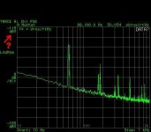
What is that -115 on top left in the pic?
20*log(noise density in nV/rtHz)
Noise voltage=noise density*SQRT(BW). For 20Hz-20KHz, SQRT(BW)~141 hence the 7uV that Bonsai mentioned, 50*141=7000nV
Noise voltage in dB=20*log(7uV)=103dB
Syn08, no challenge given. I just took your data and extrapolated the Gm from the data sheet of the 2SK246 that I have in front of me. For an Idss of 1.3 ma it is almost exactly 2mS and for 6ma, it is almost exactly 4mS. That is a factor of 2 for Gm, but a factor of 4.6 for Idss. Please put in the numbers, yourself.
Please, you are critiquing MY design method, I do have a right to respond with my own data taken directly from the spec. sheet.
Please, you are critiquing MY design method, I do have a right to respond with my own data taken directly from the spec. sheet.
A separate point, everyone, that must be addressed.
As we know, the LM329 Precision Reference has an output voltage of 6.9V, which is about 2.7 times lower voltage than the Norton Equivalent Zeners were evaluated at. To be fair, and accurate, the LM329 noise has to be multiplied by 2.7, in order to get the ACTUAL effective noise, if the reference were put up against a Norton examples. OR we could reduce the resistors in each test example by 2.7, lowering the circuit noise correspondingly. It is the only fair comparison, as any subsequent circuitry would have to multiply the LM329 noise by 2.7, just to get to the DC level being compared. You know, apples to apples, so to speak. This would give approximately 134nV/rt Hz for the typical EQUIVALENT NOISE for the LM329, in order to compare.
As we know, the LM329 Precision Reference has an output voltage of 6.9V, which is about 2.7 times lower voltage than the Norton Equivalent Zeners were evaluated at. To be fair, and accurate, the LM329 noise has to be multiplied by 2.7, in order to get the ACTUAL effective noise, if the reference were put up against a Norton examples. OR we could reduce the resistors in each test example by 2.7, lowering the circuit noise correspondingly. It is the only fair comparison, as any subsequent circuitry would have to multiply the LM329 noise by 2.7, just to get to the DC level being compared. You know, apples to apples, so to speak. This would give approximately 134nV/rt Hz for the typical EQUIVALENT NOISE for the LM329, in order to compare.
Last edited:
Anyone else want to check my work and my estimates? This is REAL engineering. It's not that hard, in this case. Almost anyone here can do it. Just get the data sheets from the internet. Look up values on the graphs contained in the data sheets, then multiply or divide, accordingly.
Anyone else want to check my work and my estimates? This is REAL engineering. It's not that hard, in this case. Almost anyone here can do it. Just get the data sheets from the internet. Look up values on the graphs contained in the data sheets, then multiply or divide, accordingly.
What you got is totally irrelevant.
1. For a fixed output voltage, the output noise does not depend on the JFET Gm (see my previous comments and experimental results about, at least now).
2. The slope of the Gm vs. Idss curve is exactly 2/Vt where Vt is the pinch voltage. Simple math on the datasheet Gm vs. Idss curve shows that it's for Vt=6V, which is at the extreme of the spec (0.7...6V)
3. Of course Vt=6V helps lowering the noise (see my previous comments about, at least now). Good luck finding 2SK246 with that pinch voltage and Idss combination.
Otherwise, I already shared my opinion about arguing with you, and that brought me a week of bench time. I'm ready to take another one, provided that my post would not vanish in thin air.
Last edited:
Just keep it civil and technical between John and you. You can argue in that manner as strong and long as you may wish. People will understand the right angle, never worry about the communal mind's ability to follow the best direction in the end. The ''VU'' meter post is getting out. No need for that.
A separate point, everyone, that must be addressed.
As we know, the LM329 Precision Reference has an output voltage of 6.9V, which is about 2.7 times lower voltage than the Norton Equivalent Zeners were evaluated at. To be fair, and accurate, the LM329 noise has to be multiplied by 2.7, in order to get the ACTUAL effective noise, if the reference were put up against a Norton examples. OR we could reduce the resistors in each test example by 2.7, lowering the circuit noise correspondingly. It is the only fair comparison, as any subsequent circuitry would have to multiply the LM329 noise by 2.7, just to get to the DC level being compared. You know, apples to apples, so to speak. This would give approximately 134nV/rt Hz for the typical EQUIVALENT NOISE for the LM329, in order to compare.
Who said you should replace your Norton with 3 x LM329? This is what I said about: http://www.diyaudio.com/forums/soli...rch-preamplifier-part-ii-190.html#post1961741
And again, using a low noise gain stage with virtually no PSRR like in the Vendetta Research RIAA preamp, and then patching this with a pathological low noise requirement for a power supply buffer is BAD engineering.
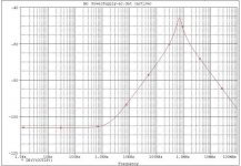
Somebody (I think it was Ikoflexer) said he never saw a regulator with 1milliOhm @10MHz simulated output impedance.
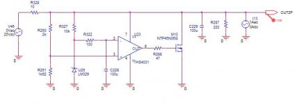
Here's an example I have posted some time ago in another thread. As you see, the output impedance peaks at 5milliOhm at around 1MHz (-40 on the Y scale is 10milliOhm), while it's under 1milliOhm at 10MHz.
I have intensively experimented this parallel regulator, as part of the HPS projects. While I have no means to measure directly the output impedance, I can tell about this regulator as having exceptional performances, if wired with force/sense, to include the PCB traces in the regulator loop. Line and load regulations are measured around -90dB. With the values in the schematic, the output noise was measured at around 100nV/rtHz (and can further be optimized, by using an even lower noise opamp as the new ADA4998, and also tweaking the filter cell around the LM329). It also has 0% overshoot at step load, I've tested this with my HP54720D 1GHz, 4Gs/sec digital scope, down to 50pS resolution.
The one and only reason I decided not to use this regulator in my HPS3.1 preamp was a thermal issue. Under overload conditions, the HPS3.1 head amp deliveres up to 200mA of current in the feedback loop. Therefore, the parallel regulator has to be able to deliver the same current. This led to an unacceptable power dissipation, heating the board and hence... significantly increasing the head amp noise. Certainly, parallel regulators are less than optimum for class AB gain stages.
Attachments
Last edited:
- Status
- Not open for further replies.
- Home
- Member Areas
- The Lounge
- John Curl's Blowtorch preamplifier part II