1audio said:How does the transient thermal change affect the signal passing through the amp? This is clearly not easy to measure with steady state tests and it may be significant. I have been reading about delay vs. temperature in very precision systems and the numbers are in the 10 pS/degree C in a carefully compensated system. I seriously doubt anyone would hear something that small as a steady state change but an abrupt change could modulate a signal enough to be audible (if we knew what was audible).
I worry the most about transient under-bias of a class AB output stage. If I have to pick my poison, I'll always go with overbias and some possible gm-doubling consequences.
Cheers,
Bob
KSTR said:Sounds like a good idea. Something like measuring small signal HF Zout during/after a power burst, by backdriving the amp with a LF current. Maybe in a high (noise) gain config to make it more readily apparent.
- Klaus
This is a good idea. A variant would be to operate the amplifier at 20 kHz at the power level that nominally yields the highest amount of crossover distortion. Then back-drive the amplifier with a low frequency at moderate power at perhaps 10 Hz. Then look at the 10 Hz modulation of the 20 kHz distortion residual on a scope. Note that the high damping factor of the amplifier under test keeps most of the low-frequency back-drive signal out of the distortion analyzer.
Cheers,
Bob
Bob Cordell said:
I worry the most about transient under-bias of a class AB output stage. If I have to pick my poison, I'll always go with overbias and some possible gm-doubling consequences.
Cheers,
Bob
Good point again. No we can discuss a measure of overbias, with respect to mentioned thermal transients as well. And soft transition.
Re: Aluminium works
Did I? Hmmmm...
kamskoma said:Nelson Pass,
Once you recommended an "how to" book about working with aluminium, do you remember the author and title of this book!
This book can be very useful for preamp DIY builders.
Did I? Hmmmm...
Re: Aluminium works
Though tube-centric, "Building Valve Amplifiers" is a very good guide to general metal-bashing for audio.
kamskoma said:Nelson Pass,
Once you recommended an "how to" book about working with aluminium, do you remember the author and title of this book!
This book can be very useful for preamp DIY builders.
Kamskoma
Though tube-centric, "Building Valve Amplifiers" is a very good guide to general metal-bashing for audio.
Well, maybe I'm missing something here, but thermal effects on THD should be quite easily investigated.
Just run a 2 tone test into the DUT, say 1kHz plus a 40kHz sine. Apply bandpass to get rid of the 40kHz. Estimate from standard 1kHz THD the additional intermodulation products and subtract. Certainly a little matlab or similar is usefull for better precision.
Have fun, Hannes
EDIT: or mount transistors on high power Peltier-elements.
Thermal transient effects
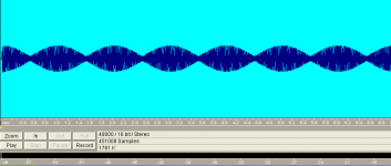
Try multitone signal 50+51Hz (beat 1Hz) with 0dB and 10k+11k with -10-20dB relative to 50+51Hz. Observe only IMD products 10k+11kHz(1kHz...), When driving amp with this signal just under limit, power is cycling from 0-100% with 1Hz, so IMD products cycling should be visible..You can try e.g 50+50,2 Hz as "base", so thermal cycling is with 5sec period.
Try multitone signal 50+51Hz (beat 1Hz) with 0dB and 10k+11k with -10-20dB relative to 50+51Hz. Observe only IMD products 10k+11kHz(1kHz...), When driving amp with this signal just under limit, power is cycling from 0-100% with 1Hz, so IMD products cycling should be visible..You can try e.g 50+50,2 Hz as "base", so thermal cycling is with 5sec period.
h_a said:Well, maybe I'm missing something here, but thermal effects on THD should be quite easily investigated.
Just run a 2 tone test into the DUT, say 1kHz plus a 40kHz sine. Apply bandpass to get rid of the 40kHz. Estimate from standard 1kHz THD the additional intermodulation products and subtract. Certainly a little matlab or similar is usefull for better precision.
Have fun, Hannes
EDIT: or mount transistors on high power Peltier-elements.
THD and IM stuff is interesting but my interest was time based modulations. They may show as sidebands but may be more audible as time shifts. Much harder to measure.
Sidebands "pumping" of IMD products 10+11kHz with period of 50+51Hz beats is clearly visible with " bad enough" amplifier on spectra in real time.They may show as sidebands but may be more audible as time shifts. Much harder to measure.
So where is impact of thermal effects on linearity? Especialy at hf (like 10+11kHz) it should be visible, or no?Have the signal, but see nothing special in a FFT.
1audio said:
THD and IM stuff is interesting but my interest was time based modulations. They may show as sidebands but may be more audible as time shifts. Much harder to measure.
I'm out of my element but I don't think the diffusion equations support waves as a solution. Analogies between electrical effects and thermal ones will fail badly at some point. jcx probably has better input on this.
If you use music with 60 BPM, it is also periodic cycled in power..But serious, if 1 or 2 seconds period between 10% and 100% power (with 10+11kHz present)have no (visible)impact on sidebands (9,11kHz) and 1kHz IMD (with properly constructed and biased amp), how can it be hearable?BTW, the test signal is periodic ....
BTW, you should use no averaging and FFT e.g. 4096 or 8192.
With underbiased amp i can see so with sugested signal sidebands "pumping" at levels between -120 to -110dB , peaks 10+11kHz at -20dB, 50Hz components peks at -6dB on spectra. Power is cycled from 1W to 100W..But is it from termal effects? Sure not.
Wavebourn said:
I have a pair of LMI-500 filters by UTC, I can bring them when I come.
Edit: I've found they are LPF actually, 60 dB/Oct, so the task is reversed: like 200 Hz to observe, 20 KHz to disturb. Not so good for phase angle observations, but who knows...
Sometimes you make do with what you have-
Start out with two oscillators, a very stable low distortion low frequency oscillator and a modulatable high frequency oscillator.
Run the lf oscillator a low level through the chain into a sensitive phase meter. Mix into the input the HF oscillator pushing the system to close to its power limits. Cycle the HF oscillator at various rates consistent with the thermal time constants in question. Pass the output through the LPF and see the effect on the phase meter comparing the input phase to the output phase.
I have read but can't cite references that the relative phase of a composite signal are not audible, however if the phase relationship is changed the change is audible. I don't know if there is any data on this.
- Status
- Not open for further replies.
- Home
- Member Areas
- The Lounge
- John Curl's Blowtorch preamplifier part II