Probably good enough for you? (referring to your phono stage)
I don't know, that's why I'm asking.
Anyway, one of the beauties in my phono stage is that it doesn't need any expensive dual or handmatched JFETs, so a J74 equivalent together with the LSK170 would do just fine.
I don't know, that's why I'm asking.
Anyway, one of the beauties in my phono stage is that it doesn't need any expensive dual or handmatched JFETs, so a J74 equivalent together with the LSK170 would do just fine.
Could you hear a difference if one was obvious? Just curious as to how you can evaluate how a component sounds when you do not believe that any differences could exist in the first place. On your web site you allow others to provide you with testimonials as to the sound quality of one of your designs, but you do not seem to agree with the possibility of sonic differences in components. I am confused.
I always thought that the self-noise of the input devices was the most important source of overall noise, that can't be fixed.
Ok, I'm in a good mood today, so here's a free lesson:
In a two stage amplifier, the input stage dominates the total noise only if the input stage gain is larger than 1/3 the total gain (closed loop if any feedback is involved, not the case with BT). Why 1/3? Because noise adds squarely and (1/3)^2~1/10, so that the second stage noise can be neglected (it's contribution to the input referred noise is small).
Now, what is the BT input JFET stage gain? It's the ratio of the drain and half of the source resistors, that is, about 1.6. And what is the BT total gain? If memory serves, is about 7.6 (ratio of the output load and half of the source resistor). The condition above is not fulfilled, so the input stage is not the dominant noise source. It's the output MOSFET noise dominating the input referred noise.
I'm not even talking here about what's the purpose of using 4 x 1nV/rtHz JFETs (equivalent to 0.5nV/rtHz), with a source equivalent noise resistor of 130ohm (that is, 1.5nV/rtHz).
Of course, if the BT schematic that was posted is incorrect, so am I.
Last edited:
The Blowtorch had a phono stage as an optional extra. The pictures of the Blowtorch show this phono stage. The visible part of the phono stage was first designed over 25 years ago, and has an equivalent noise of about 9 ohms or 0.4nV/rt Hz. It is NOT the line amp, which has a 25K pot in front of it, in any case. The input stage of the phono preamp consists of exactly the same devices that I gave to the consultant to Linear Systems, the 2SK146 and the 2S73. The actual noise limitation was the 2.5 equivalent ohms that was the effective noise of the 10 ohm wirewound pot that I initially used for self biasing the jfets and to give AC balance for lowest 2'nd harmonic distortion. The input stage current was approximately 25 ma. If I had used a 5 ohm pot, or even a 1 ohm multiturn pot, I could have even lower noise, but I might not have the range for nulling the 2'd harmonic that is present.
You are quite correct that the BT line stage is more noisy than I would like, but it is still essentially inaudible.
You are quite correct that the BT line stage is more noisy than I would like, but it is still essentially inaudible.
The Blowtorch had a phono stage as an optional extra. The pictures of the Blowtorch show this phono stage. The visible part of the phono stage was first designed over 25 years ago, and has an equivalent noise of about 9 ohms or 0.4nV/rt Hz. It is NOT the line amp, which has a 25K pot in front of it, in any case. The input stage of the phono preamp consists of exactly the same devices that I gave to the consultant to Linear Systems, the 2SK146 and the 2S73. The actual noise limitation was the 2.5 equivalent ohms that was the effective noise of the 10 ohm wirewound pot that I initially used for self biasing the jfets and to give AC balance for lowest 2'nd harmonic distortion. The input stage current was approximately 25 ma. If I had used a 5 ohm pot, or even a 1 ohm multiturn pot, I could have even lower noise, but I might not have the range for nulling the 2'd harmonic that is present.
That's news to me - thanks. So, there is a BT phono stage option, is there any difference to the Vendetta phono stage? Following your description, it seems like these differences (if any) are very small.
I think it is also important to add for those looking at the BT line stage that using very low noise JFETs is not really required in this application.
Last edited:
There's something very confusing to me here. You're talking about sub 10nV/rtHz self noise for the input stage; is the supply noise of that stage anywhere near that value? Does it matter if it's not?
For the BT line stage, having quite a poor PSRR, the supply noise matters, but as John already mentioned this is anyway largely inaudible. For very low noise designs, the input stage PSRR is a critical factor in rejecting the supply noise (harmonic -aka hum- and non-harmonic).
I have the Vendetta Research phono stage schematics, but I won't comment about, as long as it's under John's current agenda. Though, take a look at the HPS 3.1 head amp on my web site and you'll note that every measure (cascoding, local power supply, local filtering, wiring) was taken to increase the input stage PSRR and to minimize the noise impact of an already very good main regulator (Jung-Didden based, with a MOSFET as a serial regulator device).
The root HPS 3.0 design (never published) was using simple parallel regulators, but then the heat was to much to take; the board was getting hot and the noise performance degraded significantly.
My question remains unanswered John. To me it makes little sense to talk about 0.5nV/rtHz device self noise and in the same time that device sees more noise from the supply.
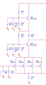
syn08? Especially it would affect your super low noise phono right? In particular, in your HPS 2.0, what is the noise between the emitter of Q202 and the drain of J203? Does it need to be as low or lower than, say, 0.5V/rtHz.
Am I missing something obvious?
Edit: oops, it seem we cross posted.
syn08? Especially it would affect your super low noise phono right? In particular, in your HPS 2.0, what is the noise between the emitter of Q202 and the drain of J203? Does it need to be as low or lower than, say, 0.5V/rtHz.
Am I missing something obvious?
Edit: oops, it seem we cross posted.
Attachments
Last edited:
Now I see what creates the confusion: Why did I use low noise jfets in the input stage, when I could have used noisier parts and gotten away with it? Well, what was available 10-12 years ago when I designed the Blowtorch? Do you remember what a 2SK389-2SJ109 set cost, 10 years ago. Answer: $2.00
Now WHY would I not use these devices, when they ALSO have the high Gm that I need to lower distortion, and great device match? They are also matched in Gm. What a combination!
Now WHY would I not use these devices, when they ALSO have the high Gm that I need to lower distortion, and great device match? They are also matched in Gm. What a combination!
I hope that many here come to understand that the 2SK389-2SJ109 combination will be sorely missed by audio designers, not JUST for their low noise, but for the close matching of the devices on chip and the easy matching of the complementary pairs, because of Gm matching with Idss by the manufacturer, and the color code screening that gives a 2:1 Idss ratio, max, compared to 10:1 for typical American devices, that did the job, previously.
Now, I see designers reverting to mosfet input devices to do the same basic circuit, with the additional noise, input capacitance, and added bias structure.
Now, I see designers reverting to mosfet input devices to do the same basic circuit, with the additional noise, input capacitance, and added bias structure.
I hope that many here come to understand that the 2SK389-2SJ109 combination will be sorely missed by audio designers, not JUST for their low noise, but for the close matching of the devices on chip and the easy matching of the complementary pairs, because of Gm matching with Idss by the manufacturer, and the color code screening that gives a 2:1 Idss ratio, max, compared to 10:1 for typical American devices, that did the job, previously.
Now, I see designers reverting to mosfet input devices to do the same basic circuit, with the additional noise, input capacitance, and added bias structure.
Indeed, N-N in K389 and P-P J109 matching is very good. However, N-P matching is nowhere easier than in a K170-J74 pair.
For the fans of hand matching, it is possible to match pairs of K170 to a better precision than in the K389 single chip device. I posted somewhere on this forum the Idss and noise distribution over a population of 200 K170 and J74 devices and, if memory serves, out of 100 devices in the same class you can get 20 pairs matched to 0.1mA and about 10 N/P quads matched at the same level. Extend the matching at 0.2mA and you get statistically 25 of the latter.
Anyway, to me, a discrete design that relies on such a good matching is a poor design. This doesn't mean that a poor design can't be a high end audio product. For the right price, you can afford to hand match JFETs to 10uA Idss precision

What Syn08 is saying is that if you have a great number, more than 100 of each device, and you are willing to individually test to get exactly the right Vgs at a specified current, you can do pretty good match, yourself. You can even do as well as some of the best 2SK389's and certainly better than the very worst 2SK389's.
However, this takes time, patience, and a lot of left over parts. This is almost EXACTLY how Mark Levinson did it, 36 years ago, when he built the first complementary differential jfet line amp modules for my client, from my design. He even hired a special worker just to do that, when the Levinson JC-2 went into production.
When it comes to really doing it right, the best way is to get a lot of 2SK389's, sort them as to their DC offset at working current, then match similar offsets by paralleling them facing each other, to make them opposite offsets. This also gives excellent thermal tracking, something the 2SK389 excels in. This is probably the best approach, but only necessary when servos are not effective.
In my original Vendetta Research SCP-1 input stage, I used a servo to lower the DC offset, BUT I still found that even with good quad matching, there was a significant amount of 2'nd harmonic, and since I ran the circuit open loop, it was necessary and useful to put a wirewound pot between the sources to null the 2'nd harmonic distortion by balancing the gains of the two sides of the complementary stage. Syn08 does this by adding global negative feedback. Something I would still not do, even today.
Syn08 does this by adding global negative feedback.
AND a very good servo. Which makes matching useless, also because there's no noise dependency on matching.
About open loop vs. NFB, don't get me started
")
- Status
- Not open for further replies.
- Home
- Member Areas
- The Lounge
- John Curl's Blowtorch preamplifier part II