What i meant is most if not all EE's never worry about the temperature of an IC as long as it doesn't reach the maximum. Resistivity and conductivity being temperature dependent will hence be different between low and high amplitude / energy signals. I know I can make an IC super efficient by simply talking a can of air, turning it upside down and spraying with the freezing air that comes out. So I propose, as I have in the past, why not attach a TEC (thermal electric cooler) and set to some dew safe temp like 15 C and see if you do not get more linear operation. This IS high end, no?
Are you not confusing efficiency with linearity?
Also, low temperature does not mean high efficieny. You can make a good case that the hotter a part, the higher it's 'efficiency'.
Jan
Well trying cooling an opamp while it is running and observe. Until a signal is large enough to heat the substrate to deltaT above ambient, you will have different local temperature profiles with different signals - Pianissimo to Sforzando. Typically those differing temp profiles affect resistivity ans conductivity. I am simply saying convert the IC package / substrate into the heat sink by cooling it, Thus decreasing junction thermal transient time etc. It seems to me, with amplifiers, massive (high thermal mass) heat sinks are used to also stabilize transient thermals but at higher and still not controlled temperatures. The thermal flux in a active region of typical IC's is quite high.
Last edited:
Well trying cooling an opamp while it is running and observe. Until a signal is large enough to heat the substrate to deltaT above ambient, you will have different local temperature profiles with different signals - Pianissimo to Sforzando. Typically those differing temp profiles affect resistivity ans conductivity. I am simply saying convert the IC package / substrate into the heat sink by cooling it, Thus decreasing junction thermal transient time etc. It seems to me, with amplifiers, massive (high thermal mass) heat sinks are used to also stabilize transient thermals but at higher and still not controlled temperatures. The thermal flux in a active region of typical IC's is quite high.
You DO know that ICs are carefully engineered to cancel thermal transients across the die, I guess?
Also, thermal transients are not depending on the final temp - they are transients, as the name implies.
Could you also explain what this has to do with linearity, by actually addressing the question?
Jan
So I propose, as I have in the past, why not attach a TEC (thermal electric cooler) and set to some dew safe temp like 15 C and see if you do not get more linear operation. This IS high end, no?
Because this is no different than attaching an enormous heat sink? The difference between 300K and 285K case temp is fairly trivial, and holding the case at a constant temp has a tiny (if any) effect on the Theta Jc of the individual components inside.
In a small signal application you would have to abuse a little 8-legs by trying to drive a heavy load unnecessarily, for instance, to create a significant rise above ambient. An experiment anyone can try, as long as 741's still have the built in thermal distortion as Solomon showed. Just pop a block of copper on top of the case and see if it changes.
Last edited:
TEC is only of any use if it is directly attached to the silicon die itself.
The top of the die.
")
Hire someone to do an easy proof-of-concept experiment:
Measure the linearity of a PCB-level audio circuit. Perhaps THD or IMD are easy-to-measure indications of linearity.
Now drop the PCB into a bucket of 0 degree F (-18 degree C) mineral oil and measure linearity again, while submerged. Don't worry, mineral oil is an excellent insulator. Did linearity get better? worse? no change?
If it's really important to you, you can have the answer in less than a day.
To be fair I understand where CC is coming from, but I think the problems don't simply translate from one domain to the other. Layout dependent thermal nonlinearities on small signal IC's were identified 40yr. ago and design techniques were established. There is a very interesting paper from RCA Labs IIRC where an NTSC color decoder IC required a complete 3D thermal simulation. There was also a paper by the great Alberto Bilotti (sp?) where he solved the equations in closed form! (no computers). So we had awareness, symmetry, and rules of thumb. Thin films then also had to be formulated to eliminate thermal distortion.
Yes, to be 100% precise.
But then how to avoid the bond wires ?
Perhaps should use BGA or similar packaging.
Patrick
Maybe you need a die with small holes, so you can circulate the coolant through the die.
Update on the DAC3 review, Charles Hansen has really flamed on in the comments. He clearly didn't like the review!
where is this review? and Hansen flame? I would like to read it as I have DAC3.
THx-RNMarsh
Yes, the Benchmark Media power amp is designed to be very high slew rate.
last time I looked -- it was 17v/usec
-Richard
It's the Stereophile review Bill mentioned recently. Some reader comments have started coming in, is all. Benchmark DAC3 HGC D/A preamplifier-headphone amplifier | Stereophile.com
last time I looked -- it was 17v/usec
It looks like you might be right about that. Doesn't look like Benchmark specifies it either.
There was some article somewhere I read talking about the DA-101 distribution amp they used to make which I thought was based on some video amplifier topology, and which could be used to drive speakers. The AHB2 was said to have been designed to provide similar performance at higher power. Can't find everything I thought there was to the story, but did find this:
The Technology Behind the AHB2 Power Amplifier: An Interview with Benchmark Media's John Siau - Poor Audiophile
In a small signal application you would have to abuse a little 8-legs by trying to drive a heavy load unnecessarily, for instance, to create a significant rise above ambient. An experiment anyone can try, as long as 741's still have the built in thermal distortion as Solomon showed. Just pop a block of copper on top of the case and see if it changes.
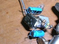
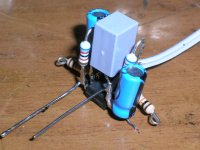
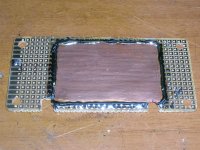
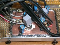
dead bug construction over copper foil, thermo-conductive paste in between
(belt and suspenders approach, just in case
)George
Attachments
where is this review? and Hansen flame? I would like to read it as I have DAC3.
THx-RNMarsh
Benchmark DAC3 HGC D/A preamplifier-headphone amplifier | Stereophile.com
It's kind of sad that Charles still uses extreme hyperbole like the burn in comment. It's true that FR4 can take 24hr. to bleed off charge but that's at 10**12 Ohm resistance level not 1k.
Yes, but local temperatures throughout the chip will vary with load if not die bonded. You would also have to similarly push the input diff pair and ops into heavy bias to reduce transient thermal gradients (versus steady state). The die temp does vary away from the package temp by a decent margin.
If you want to do a tec right, it's going to be to go full on vacuum sealed and cooled to -40/-50 C. Otherwise a heat spreader/heatsink.
If you want to do a tec right, it's going to be to go full on vacuum sealed and cooled to -40/-50 C. Otherwise a heat spreader/heatsink.
- Status
- Not open for further replies.
- Home
- Member Areas
- The Lounge
- John Curl's Blowtorch preamplifier part II