That's amazing, considering decent metal films were around then. But those were pretty resistors.Having seen a copy, as I recall Allen Bradley "Hot Molded" carbon composition 5% 1/2 watt resistors in an R-2R ladder. But selected for accuracy. It was also only nine bits linear with a second 7 bit stage to get to 16 bits. That was copied by Sony when they made their first A/D converters including the chip whose number I forget, that went into all the first generation recorders.
I once cannibalized a physics dept. DAC that was used to raster-scan some particle-detector-related display, I think in order to digitize photographic film. Bit switches took entire cards, and the resistor array consisted of Vishay bulk foil parts in hermetically sealed cases, with the whole array in an oil bath. I think it managed 14 bit resolution. I still have some of the resistors tossing around.
And, if we correct the problem at the source... ripple and noise from the PS... it will relax the psrr needed in the amplifier. Doing both, a clean PS source and good psrr is not so bad either.
THx-RNMarsh
Generally better to get it from the circuit if you can. Obviously becomes a problem in high gain preamps, where you're missing out on that lovely loop gain.
Then again there are those who claim that any amplifier that doesn't become a PSU project is doing it wrong. As Scott likes to remind us: the rest of the planet likes low voltage and low power.
That's amazing, considering decent metal films were around then. But those were pretty resistors.
I once cannibalized a physics dept. DAC that was used to raster-scan some particle-detector-related display, I think in order to digitize photographic film. Bit switches took entire cards, and the resistor array consisted of Vishay bulk foil parts in hermetically sealed cases, with the whole array in an oil bath. I think it managed 14 bit resolution. I still have some of the resistors tossing around.
Vishay started in 1962. Stockham was building his converters in 1968. May have had Dale style red 1% Mil-spec resistors but bulk-films were probably not well enough available or priced in reason then.
I can't remember clearly if there were any 1% ers. Seem to also recall TO-5 cased transistors. Was about 1 rack unit high by about 14" deep. But that was a while ago and my memory is... what were we discussing?
I recall a picture that looked more like a 5 1/4" rack-mountable chassis. This was in the initial LP, was it Telarc? before CDs were available iirc.
I would doubt that he would compromise on less than the best resistors just based on cost, but who knows. Maybe his funding was running out.
EDIT: even a grad student in the Astronomy Dept. was using custom Vishays for a photometer preamp in about 1968, when I began working there.
I would doubt that he would compromise on less than the best resistors just based on cost, but who knows. Maybe his funding was running out.
EDIT: even a grad student in the Astronomy Dept. was using custom Vishays for a photometer preamp in about 1968, when I began working there.
I recall a picture that looked more like a 5 1/4" rack-mountable chassis. This was in the initial LP, was it Telarc? before CDs were available iirc.
I would doubt that he would compromise on less than the best resistors just based on cost, but who knows. Maybe his funding was running out.
EDIT: even a grad student in the Astronomy Dept. was using custom Vishays for a photometer preamp in about 1968, when I began working there.
I certainly could have missed the Vishay's, as I was amused go see the Allen Bradlèys, but I didn't run into them in the 70's. Might have been two rack units but I recall it was small for the day. One channel per chassis.
Suspicion is that he was rather budget bound. Of course I was looking at a copy.
Late 70's I did buy a Micronetworks 16 bit D/A. They were amused it wasn't for military use.
Cap ESR, ESL and trace inductances are the great leveller of practical PSRR in my experience as is pF coupling of supply artifacts into hi-Z nodes around the circuit.
.. and that's where RF design / layout techniques come in handy!
")
That's amazing, considering decent metal films were around then. But those were pretty resistors.
I once cannibalized a physics dept. DAC that was used to raster-scan some particle-detector-related display, I think in order to digitize photographic film. Bit switches took entire cards, and the resistor array consisted of Vishay bulk foil parts in hermetically sealed cases, with the whole array in an oil bath. I think it managed 14 bit resolution. I still have some of the resistors tossing around.
I used to cobble parts out of missile program boards that had R2R's made out of wire wound .1% resistors and filters full of 1% film caps. There are current switch architectures where the inductance is not a primary problem.
Thermal charge and discharge of caps.... release spurious signals
I also think so.... and trace/wiring x-talk etc.
-----------------
In another area where cap coupling may still be used.... high Z circuits... maybe cap microphone amps and filters, for example.... Still going thru my file cabinet of old data files is this gem...
Spurious Signal Generation in Plastic Film Capacitors. by Jon.W.Borough in an issue of IEEE Transactions on Parts, Hybrids and Packaging. Dec 1977, Vol PHP-13, No.4; I have foot-noted this before but here we have the affects of DA in caps which causes spurious signal generation under thermal charge/discharge cycles.
THx-RNMarsh
Cap ESR, ESL and trace inductances are the great leveller of practical PSRR in my experience as is pF coupling of supply artifacts into hi-Z nodes around the circuit.
I also think so.... and trace/wiring x-talk etc.
-----------------
In another area where cap coupling may still be used.... high Z circuits... maybe cap microphone amps and filters, for example.... Still going thru my file cabinet of old data files is this gem...
Spurious Signal Generation in Plastic Film Capacitors. by Jon.W.Borough in an issue of IEEE Transactions on Parts, Hybrids and Packaging. Dec 1977, Vol PHP-13, No.4; I have foot-noted this before but here we have the affects of DA in caps which causes spurious signal generation under thermal charge/discharge cycles.
THx-RNMarsh
Last edited:
Filters still make problems.
Sure can. Your phono pre-amp's filter could put strain on a SMPS device.
99.9% of filtration is done bad, within equipment, so it's probably smarter to avoid it for those that don't know how to do it (the majority of high end audio does just that). The only place anyone seems to make it worth it is in a DAC; mostly because they have almost zero current requirements.
I also think so.... and trace/wiring x-talk etc.
-----------------
In another area where cap coupling may still be used.... high Z circuits... maybe cap microphone amps and filters, for example.... Still going thru my file cabinet of old data files is this gem...
Spurious Signal Generation in Plastic Film Capacitors. by Jon.W.Borough in an issue of IEEE Transactions on Parts, Hybrids and Packaging. Dec 1977, Vol PHP-13, No.4; I have foot-noted this before but here we have the affects of DA in caps which causes spurious signal generation under thermal charge/discharge cycles.
THx-RNMarsh
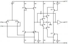
One can go MUCH further by design ...A new audio amplifier topology with push-pull transimpedance stage - Part 1: Introduction | EE Times
The TIS/VAS (Q7-12) Fig 5 is fully ground referenced. Typically , this
stage is referenced to the "dirty rails".
We can then "hide" the input stage (Q1-6) behind a low voltage regulated supply.
Matters not whether it is CFA/VFA .
I was doubtful at first - it works like dream.
PS - I do agree layout /loop area/component choice is important. But
only to enhance the main design.
OS
Attachments
That is a nice way to handle it....
and, Demystifying PSRR in an OpAmp - Technical Community
?/
But also: http://electronics.stackexchange.com/questions/14176/relationship-between-psrr-and-gain
THx-RNMarsh
and, Demystifying PSRR in an OpAmp - Technical Community
?/
But also: http://electronics.stackexchange.com/questions/14176/relationship-between-psrr-and-gain
THx-RNMarsh
Last edited:
Might have been two rack units but I recall it was small for the day. One channel per chassis.
Suspicion is that he was rather budget bound.
They had two racks full when I visited them in the late '70s. If they were budget-bound, it wasn't evident in their lab or demo area, both of which were quite opulent. I was pretty impressed with the sound they were getting, and that was when my ears were young.
That is a nice way to handle it....
But also: power supply - Relationship between PSRR and gain - Electrical Engineering Stack Exchange
THx-RNMarsh
Interesting , they are debating whether NFB in closed loop will increase
the PSRR with equations.
OEM's and Wiki have differing opinions on this.My simulator (and the amps) say that NFB is a major player.
The beta enhanced "blameless" or Hawksford VAS have weak PSRR(-40db) by themselves.
That Groner TIS/VAS only -70db by itself.
But , after you wrap the NFB around the complete input stage -40 becomes
-110db and -70 almost -130 (or better at 1K).
In your link , they debated OLG vs. CLG. HF PSRR is quite predictable by the
amount of CLG margin at these higher frequencies. LF PSRR is more
dependent on rail R/C and the native (pre-NFB) cancellation in the VAS.
The output stage is fully dependent on NFB for ripple cancellation.
PS- a good design should perform two duties. Be both a audio amplifier
and a good linear feedback regulator.
OS
They had two racks full when I visited them in the late '70s. If they were budget-bound, it wasn't evident in their lab or demo area, both of which were quite opulent. I was pretty impressed with the sound they were getting, and that was when my ears were young.
16 channels would have taken two racks. Did you look inside the gear or even at the schematics?
- Status
- Not open for further replies.
- Home
- Member Areas
- The Lounge
- John Curl's Blowtorch preamplifier part II