I would be concerned about the weird artifacts your probe is creating. It's creating all kinds of harmonics. Zero crossing also has a strange fast slew, perhaps part of the hysteresis of the core being used.I did a quick check of the sensitivity of the probe. I used a 100 ohm resistor and looked at the current through it and the voltage across it. Voltage is channel 2 or yellow. It's frequency response is horrible, but it does go lower than I thought.
I assume the core is non conductive, but can you tell us?
Does closing the wire loop between the core and the coax change anything? If you insulate the ends so you can wind the enameled wire very tightly to reduce parasitics, would that help?
Note the bump in the curve from the silicon carbide rectifier, I read this as weird ESR. So I would use them for low current use only, but based on the price probably not even that.
I wonder if that is heating of the junction causing a quick drop in vf at the leading edge of the pulse.
jn
I would be concerned about the weird artifacts your probe is creating. It's creating all kinds of harmonics. Zero crossing also has a strange fast slew, perhaps part of the hysteresis of the core being used.
I did twist the lead wires before today's runs, no difference noted.
I assume the core is non conductive, but can you tell us?
Does closing the wire loop between the core and the coax change anything? If you insulate the ends so you can wind the enameled wire very tightly to reduce parasitics, would that help?
I wonder if that is heating of the junction causing a quick drop in vf at the leading edge of the pulse.
jn
The core is nonconductive. It is the slug out of a TV horizontal oscillator coil. I did it as a first pass on something better than my Tek Hall effect sensor or my unlabeled "RF" one. This not very good one is giving me really nice examples of the problem areas. It is about 3 mV per mA at 120 Hz and gets better higher and then gets really funky. I have ordered some cores that should be more accurate, but the images are really quite interesting. Note no absolute values given. (BTY you almost gave away the reason why many ferrite cores "Sound Bad." That is also on my list of things to avoid. Have you ever measured how much distortion a ferrite core can actually make?)
Ed I don't need to look at the graphs, I only reacted on your statement that there's almost no difference between a 1N4007 and a fast diode.
Jan
But Jan I thought you knew my sense of humor!
")
Last edited:
When you make the cap (very) large, the charge pulses get narrower and higher, and the ripple edges get much sharper, meaning: many more higher harmonic components. And regs and amps are less well able to suppress higher frequency junk. So there's a good rationale for your observations.
Hi Jan,
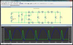
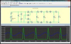
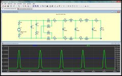
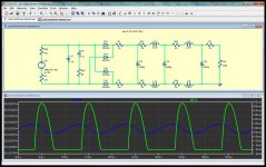
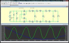
Did some spice research show current pulses into different caps etc including two methods of broadening the width of the current pulses.
100uF caps
Attachments
Last edited:
An interesting test is to place a battery powered AM radio on top of the power transformer tuned in between stations, and then place a .1uf or .01uf film cap across the secondary of the transformer. You can hear the reduction of "Buzz".
Good work Ed on your measurements.
Good work Ed on your measurements.
My conclusions are
Increasing the size of the caps makes very little difference to the height and width of the current pulse.
Increasing the voltage and adding resistors substantially decreases the height and increases the width of the pulses.
Increasing the voltage and adding ( huge ) inductors gives the most ideal current always on situation ( via one or other diodes ) but for a low current supply - like the one I am just about to build - the inductors have to be impractically large to achieve this.
Unless anyone can offer other ideas I think I will opt for series resistors.
How much current ?My conclusions are
Increasing the size of the caps makes very little difference to the height and width of the current pulse.
Increasing the voltage and adding resistors substantially decreases the height and increases the width of the pulses.
Increasing the voltage and adding ( huge ) inductors gives the most ideal current always on situation ( via one or other diodes ) but for a low current supply - like the one I am just about to build - the inductors have to be impractically large to achieve this.
Unless anyone can offer other ideas I think I will opt for series resistors.
Chokes of that rating are not that costly but do need space (volume ) 30H is not that big . If you have the room 100h is easy to be found . That what I use in tube supplies of that current needs in preamp. Just my experience so far . That much of a choke slows down the current pulses at the final cap nicely .20 - 30mA max
The charging current only equals the discharged current. The charging time is determined by the current available. That is mostly a function of the transformer current capacity. Once the filter capacitor is large enough to require maximum current then dV/dT = i/C.
The definition of capacitance is C = q/V. This yields CV = q. The first derivative is C dV/dT + V dC/dT = dq/dT. As in an ideal capacitor there is no change in C (dC) and dq/dT is defined as i. You get the ripple equation.
The definition of capacitance is C = q/V. This yields CV = q. The first derivative is C dV/dT + V dC/dT = dq/dT. As in an ideal capacitor there is no change in C (dC) and dq/dT is defined as i. You get the ripple equation.
Here is one US supplier: Triad Magnetics Product Specs They don't have your exact choke but they do have a 6H 200 mA inductor. It weighs 2 Lb (1 Kg) and is stocked at Mouser for $23 ea. You are pretty assured of continuous conduction with 6H. It also has a DCR of 150 Ohms. That translates into 15V before you get to the cap. And with a choke input supply the output voltage is approx .707 X the RMS voltage going in. However $80 for two supplies for just that part quickly gets the BOM in the uber premium range. And they are not wound with 6/9 copper even. I would look for a small shop that could make a bifilar inductor so you would have one chunk of iron for both rails. Use it in normal mode, common mode won't do much.
- Status
- Not open for further replies.
- Home
- Member Areas
- The Lounge
- John Curl's Blowtorch preamplifier part II