Jan,
For a "tiny" transformer to achieve the same effect of a big transformer and AC side choke the leakage inductance must be so large that the accompanying radiated field would make the exercise useless.
Rather, I would use a "tiny" capacitor and bite the bullet on the power dissipation of the downstream regulator.
Look at it this way: instead of seeking for the lowest voltage ripple amplitude alone, you design the system for low voltage AND current ripple amplitude and least harmonics in the voltage AND current waveforms.
The voltage regulator can attenuate any reasonable voltage ripple if its frequency content is narrow band. This is where you want your switches (diodes) to be as low noise as possible. The goal is to limit the noise to the fundamental frequency and very few harmonics. Diodes are noisy at much higher frequencies that are not correlated with the mains frequency.
Giorgio
Thanks, sounds very sensible.
Jan
Jan,
Rather, I would use a "tiny" capacitor and bite the bullet on the power dissipation of the downstream regulator.
Giorgio
I'm probably misunderstanding this quote but, this is an approach I've found sonically great for years. Smaller caps (good caps) actually improve the sound. I won't speculate as to why, because I've been told I'm wrong, and I'm sure its not appliciple to stuff I'm not building (single-ended designs), but building and listening never hurt as an approach to checking out the tried and true.
If I didn't misinterpret it, it's nice to read that someone else is checking out the oddities.
Cheap seat observations, again.
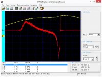
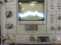
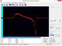
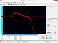
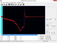
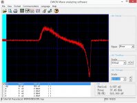
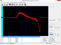
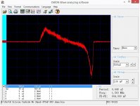
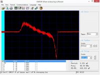
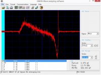
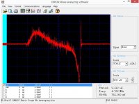
Attached are some images of my diode noise measurements,
The circuit is a 24 volt single coil from a 25VA torroid transformer feeding a 1N4007 diode bridge that is loaded by a 600 ohm resistor. About 36 volts DC. A 12,000 uF bank of capacitors can be switched in as can a 1 uF capacitor across the transformer.
First six images look at the current through one of the diodes.
First is AC trigger waveform with the basic setup. Second is a closeup of the diode switch off spike. Third is the whole cycle with the 12,000 uF capacitor bank added and the fourth scope image is with a 1 uF snubber across just the transformer secondary.
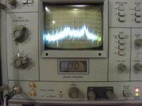
Next is the RF spectrum without the snubber and then with. Note the spikes are a 1 MHz marker showing that we are looking at about a 15 Mhz bandwidth.
Then is a close up of the test card and my sensor. Last is the preamp used to get these images. Note it is built "Flying Bug" style!
What I note is that you can see the turn on surge also lets line noise in. The surge increases with a larger filter capacitor. The snubber has decent effect on the diodes, but not total.
The RF spectrum shows how broadband the noise actually is and that some is diode switching and other line noise.
ES
The circuit is a 24 volt single coil from a 25VA torroid transformer feeding a 1N4007 diode bridge that is loaded by a 600 ohm resistor. About 36 volts DC. A 12,000 uF bank of capacitors can be switched in as can a 1 uF capacitor across the transformer.
First six images look at the current through one of the diodes.
First is AC trigger waveform with the basic setup. Second is a closeup of the diode switch off spike. Third is the whole cycle with the 12,000 uF capacitor bank added and the fourth scope image is with a 1 uF snubber across just the transformer secondary.
Next is the RF spectrum without the snubber and then with. Note the spikes are a 1 MHz marker showing that we are looking at about a 15 Mhz bandwidth.
Then is a close up of the test card and my sensor. Last is the preamp used to get these images. Note it is built "Flying Bug" style!
What I note is that you can see the turn on surge also lets line noise in. The surge increases with a larger filter capacitor. The snubber has decent effect on the diodes, but not total.
The RF spectrum shows how broadband the noise actually is and that some is diode switching and other line noise.
ES
Attachments
-
 Diode Noise 470 uF 600 ohm 24 vac 25VA.jpg139.4 KB · Views: 254
 -
 DSCF0027.jpg640.3 KB · Views: 103
 -
 DSCF0026.jpg854.7 KB · Views: 101
 -
 DSCF0024.jpg843.8 KB · Views: 82
 -
 DSCF0025.jpg828.8 KB · Views: 212
 -
 Diode noise snubbed.jpg134.5 KB · Views: 209
 -
 Diode Noise 12470 uf Cap.jpg138.2 KB · Views: 248
 -
 Diode Noise Close up.jpg134.5 KB · Views: 251
Ed:
What is the calibration constant current to voltage on the measurements?
I see the noise floor increases during the conduction cycle but I must ask how to confirm that's line noise and not something else that causing the fuzz in the waveform. The fuzz seems pretty uniform when the diode is conducting which is not what I usually see when looking at line noise.
At the risk of it getting misinterpreted, there is a good article on passive intermodulation distortion here: AWT Global : PIM: Components, Material, Handling & Testing : Article The issues of connector quality and cleanliness are probably quite valid for audio. The other issues causing IM probably do not apply.
At the risk of it getting misinterpreted, there is a good article on passive intermodulation distortion here: AWT Global : PIM: Components, Material, Handling & Testing : Article The issues of connector quality and cleanliness are probably quite valid for audio. The other issues causing IM probably do not apply.
Good reading, well done, Demian.
Now I take the risk of being misinterpreted: a good part of this has been known for a long time. I read a few texts in popular mags during the mid-70ies, suggesting that for best performance we should clean our RCA Cinch connectors, both male and female, at least once a year, preferably twice. Strictly with cotton buds and medicinal alcohol. With a warning that some connectors may not be able to accept the standatd cotton bud, in which case we will have to make our own, using toothpicks and cotton, sort of roll it together at the required size.
Call me superstitious, but I took that advice and have done by it ever since. And I am always amazed with the muck and grime I find on the cotton buds every time I do that. Twice a year.
Since they are male and female plugs, I am surprised I haven't found any traces of clap so far, what with all that penetration going on.

Last edited:
I'm probably misunderstanding this quote but, this is an approach I've found sonically great for years. Smaller caps (good caps) actually improve the sound. I won't speculate as to why, because I've been told I'm wrong, and I'm sure its not appliciple to stuff I'm not building (single-ended designs), but building and listening never hurt as an approach to checking out the tried and true.
If I didn't misinterpret it, it's nice to read that someone else is checking out the oddities.
Cheap seat observations, again.
Small caps do increase the ripple, but it is almost all 100/120Hz ripple.
Both regulators and amps are generally very good in supressing lf junk.
When you make the cap (very) large, the charge pulses get narrower and higher, and the ripple edges get much sharper, meaning: many more higher harmonic components. And regs and amps are less well able to suppress higher frequency junk. So there's a good rationale for your observations.
But a small cap with high ripple level does mean that you need more reserve at the reg input so more reg dissipation.
Jan

I'm probably misunderstanding this quote but, this is an approach I've found sonically great for years. Smaller caps (good caps) actually improve the sound. I won't speculate as to why, because I've been told I'm wrong, and I'm sure its not appliciple to stuff I'm not building (single-ended designs), but building and listening never hurt as an approach to checking out the tried and true.
If I didn't misinterpret it, it's nice to read that someone else is checking out the oddities.
Cheap seat observations, again.
Large caps are more likely to resonate with film bypass, which can cause problems. Smaller caps have more ESR which will help to damp resonances. This may be another reason it helps.
Ed:
What is the calibration constant current to voltage on the measurements?
I see the noise floor increases during the conduction cycle but I must ask how to confirm that's line noise and not something else that causing the fuzz in the waveform. The fuzz seems pretty uniform when the diode is conducting which is not what I usually see when looking at line noise.
If you look at the rf spectrum there appears to be an LF roll off. When I get the chance I'll run a current curve.
As I have a line noise generator or two, it is a simple matter of changing the AC line noise and watching it track.
So you like Dick have added to my work load.
As to the article it talks about electron flow when it should be charge. Scott will get confused again. The careful reader will not the issue occurs at lower levels even inside conductors that have metallurgical impurities or even micro cracking. So all it does is open last months can of worms.
Last edited:
Large caps are more likely to resonate with film bypass, which can cause problems. Smaller caps have more ESR which will help to damp resonances. This may be another reason it helps.
Yes, remember how data sheets on early 3 pin voltage regulators warned not to use a low esr cap on the output, which could cause instablity. They recommended a lousy high esr cheap tantalum instead.
A low ESR cap causes the regulator pass transistor pole to migrate down in frequency and up in magnitude so that the loop gain is then >1 at more than 180 degrees phase shift, causing ringing with step loads and in some cases oscillation.
A high ESR cap means the pole does not migrate down as much, and stability is assured. Keep in mind, early IC regs had crap power transistors - and especially PNP.
Some of the newer regs have very fast loop response and are tolerant of the input and output cap ESR.
A high ESR cap means the pole does not migrate down as much, and stability is assured. Keep in mind, early IC regs had crap power transistors - and especially PNP.
Some of the newer regs have very fast loop response and are tolerant of the input and output cap ESR.
A low ESR cap causes the regulator pass transistor pole to migrate down in frequency and up in magnitude so that the loop gain is then >1 at more than 180 degrees phase shift, causing ringing with step loads and in some cases oscillation.
A high ESR cap means the pole does not migrate down as much, and stability is assured. Keep in mind, early IC regs had crap power transistors - and especially PNP.
Some of the newer regs have very fast loop response and are tolerant of the input and output cap ESR.
Yes, as I recall, Kemet used to make some of the "best" lousy tantalum caps.
Before you diss tanalum caps as crappy do some homework http://www.vishay.com/docs/40080/tr3.pdf
http://www.vishay.com/docs/40080/tr3.pdf
They do have their uses and they can have the lowest ESR for volume of any cap. They can also be really expensive, and not for audiophile reasons. The down side it that they can have high distortion when there is a signal voltage gradient across them.
The LM317 is not too picky but you should pay attention. Its the LDO regulators that are really sensitive. Here is all you ever wanted to learn about linear regulators: http://www.ti.com/lit/an/snva020b/snva020b.pdf and here is how to measure the parameters: http://www.omicron-lab.com/fileadmin/assets/customer_examples/ESR_Requirements.pdf
A low ESR cap causes the regulator pass transistor pole to migrate down in frequency and up in magnitude so that the loop gain is then >1 at more than 180 degrees phase shift, causing ringing with step loads and in some cases oscillation.
A high ESR cap means the pole does not migrate down as much, and stability is assured. Keep in mind, early IC regs had crap power transistors - and especially PNP.
Some of the newer regs have very fast loop response and are tolerant of the input and output cap ESR.
Yes indeed, you now see newer regs advertised as 'stable with low-ESR caps'!
Jan
Demian,
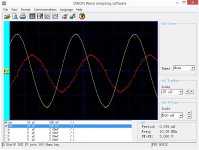
I did a quick check of the sensitivity of the probe. I used a 100 ohm resistor and looked at the current through it and the voltage across it. Voltage is channel 2 or yellow. It's frequency response is horrible, but it does go lower than I thought. I tried my noise maker box on the AC line and it worked so well the scope no longer could talk to the computer. So I took off the signal averaging and am just showing single traces, I think you'll find the noise is nicely noisier.
I also looked at the way to snub using small capacitors directly across the diodes, as you can see the 47 pF capacitors did let in a bit more noise but had no effect on the spike in the frequency range handled by this measuring method. The 1 uF across the transformer was more effective and knocked down the noise a bit.
Attached are a few pictures, as you can see there is virtually no difference between the turn off spikes from a 1n4007 and any of the faster diodes>>>> Note the bump in the curve from the silicon carbide rectifier, I read this as weird ESR. So I would use them for low current use only, but based on the price probably not even that.
I did a quick check of the sensitivity of the probe. I used a 100 ohm resistor and looked at the current through it and the voltage across it. Voltage is channel 2 or yellow. It's frequency response is horrible, but it does go lower than I thought. I tried my noise maker box on the AC line and it worked so well the scope no longer could talk to the computer. So I took off the signal averaging and am just showing single traces, I think you'll find the noise is nicely noisier.
I also looked at the way to snub using small capacitors directly across the diodes, as you can see the 47 pF capacitors did let in a bit more noise but had no effect on the spike in the frequency range handled by this measuring method. The 1 uF across the transformer was more effective and knocked down the noise a bit.
Attached are a few pictures, as you can see there is virtually no difference between the turn off spikes from a 1n4007 and any of the faster diodes>>>>
Note the bump in the curve from the silicon carbide rectifier, I read this as weird ESR. So I would use them for low current use only, but based on the price probably not even that.Attachments
-
 Basic Setup With Fairchild Fast Diodes.jpg136.9 KB · Views: 71
 -
 Basic Setup With On Semi MUR860 Diodes.jpg127.3 KB · Views: 178
 -
 Basic setup 24 VAC 600 Ohm 470 uF With Silicon Carbide Rectifiers.jpg132.8 KB · Views: 187
 -
 47 pF per diode and 1 uf Transformer snubber 1N4007 24VC 600 Ohms 470 Uf No Scope Average.jpg133.7 KB · Views: 185
 -
 47 pF per diode snubber 1N4007 24VC 600 Ohms 470 Uf No Scope Average.jpg135 KB · Views: 178
 -
 1N4007 24VC 600 Ohms 470 Uf No Scope Average.jpg139.3 KB · Views: 183
 -
 Calibration Fluke 100 ohms 1 Volt Yellow Red probe output theough 20 db preamp.jpg144.9 KB · Views: 73
Last edited:
as you can see there is virtually no difference between the turn off spikes from a 1n4007 and any of the faster diodes>>>>
That would make me suspicious....
Jan
That would make me suspicious....
Jan
Jan,
Are there optometrists around where you live? Please take a look at the curves. Remember all absolutes are wrong.
ES
- Status
- Not open for further replies.
- Home
- Member Areas
- The Lounge
- John Curl's Blowtorch preamplifier part II