John
I always make a fool of myself when I communicate in English
George
Me too.
They wanted me to take english as a second language freshman year. They still to this day, do not believe it was my primary one.
jn
We don't always agree. On this point we do agree!jneutron said:I thought we didn't agree much??
Anyone who has doubts about the difference in experiments between data and information need simply sit in on an undergraduate lab class. There you will see rows of students happily misconnecting instruments, gaily plugging numbers into the wrong formulas, and (in EE, but hopefully not physics) innocently plotting graphs with no error bars. Common mistakes include failing to distinguish between PSUs and sig gens (both are voltage sources, I suppose), between 'scopes and spectrum analysers (both display a trace), between ratios and dB (both express a ratio), between gain and signal level (both can be expressed - loosely - in dB). Remember that in 2-3 years time almost all of these will be graduate engineers, paid to develop the next generation of technology.
Such experience makes me cautious about any claims to measure something which theory says should not happen. (And even more cautious about those people who seem to thinks themselves capable to 'measure' things without instruments!) Having said that, we need to remember that the real world is not as simple as theory sometimes implies (but the theory is fine, it is our approximations which fall short of reality) - this is why it is important to be able to make order of magnitude estimates for phenomena. Back-of-envelope calculations can dismiss many silly claims, while rendering others sufficiently plausible that careful experiments are needed to deal with them.
So, now we've changed the subject?? Crosstalk of two balanced shielded cables is not the same as solenoidal inductance. I guess we can assume you gave up on that, and are now going after crosstalk...excellent, as that is exactly in line with my previous discussion about lenz, eddy, coupling, and dispersion. It requires field spillage, which is crosstalk..
What is the field termination impedance for a balanced mike?
What is the shield coverage for the cables you just tested?
Where is the schematic? Did you drive balanced and receive balanced?
When confronted with test results which seem inconsistent, you have to approach it in a logical fashion. You're jumping about in your presentation.
P.S. These days when I do lectures at Universities I talk to faculty & graduate students.
Now, is this statement about the previous phase plots?
It was indeed weird that it happened at the exact same spot. You should have run a sine into it and scoped the output, then sweep it through the point where it goes nuts. edit: you must keep the exact same drive and termination impedance however, as it may be important to keep the reflection coefficients at both ends the exact same as the AP does.
The phase droop upper band is the most interesting, disregarding the huge jumps, because the amplitude doesn't change much. What you need to do is a variable frequency TDR. I don't suppose you have a modified RF bridge, do you? An alternate approach would be a low inductance CVR and the drive end ground, then scope the line phase.
If you peruse Cyril Bateman's article on this, it may make more sense to you.
jn
ps... Ed, in case you haven't figured it out yet, I commend and think very highly of you on your questions, your tests, your willingness to bring up various notions as possible explanations. I find discussion/debate with you very refreshing, and prefer this to a world of no discussion. Thank you.
I do have two TDR's both audio & RF bridges, etc.
The issue was does coiling a microphone cord make a difference. The answer is it does.
Now as how to measure parameters in a cloudy environment is an issue I will not discuss. One follower mentioned it was not nice to say I know something but can't tell you due to proprietary interests. So I will not say anything.
Except when you coil a microphone cord it does change the results!
Last edited:
Nice. Care to discuss what measurements to do, what controls, what theory, how to test it?I do have two TDR's both audio & RF bridges, etc.
The issue was does coiling a microphone cord make a difference.
No, this was the issue (how quickly you forget)
I stated that coiling the mike cable does not increase the inductance.
In response, you posted:
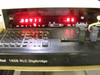
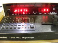
Then, you posted pictures of tests of inductance to prove your point:Yes it does! Theory says no, measurements say yes! Now for a small coil it is very small, but for a 500' spool it really is a big difference.
A photo essay for Scott. 45' WPW 291 on a spool and uncoiled.
Plastic spool of wire.
Footage marking end connected to bridge.
Reading uncoiled
Footage marking at far end.
Reading recoiled.
Then you claimed that the number of turns is the reason you expected readings in the mH range.
Here's your words to scott.
"" I know from practice there is as the twist cancellation is not perfect. It also goes up with number of turns squared. So for a full metal spool I expect results in the mH range, which will drop 10,000 hertz by more than 3 db. These are observed results."
Then you said:
Which is 3 orders of magnitude lower than what you showed a picture of.1K parallel mode. One end shorted. 6.7 ish uH result.
And now, you have backed off from your position that "coiling a mike cord increases it's inductance", and now are discussing crosstalk (which I detailed at length on the effects of such), and to top it off, you now post as if I've stated coiling can't have an effect. And right after I detailed exactly why it could, and what you needed to measure.
A rather disingenuous tact Ed. It's all in the posts.
And now, I've no clue as to how to interpret this gem:
Is it raining there? What does the weather have to do with this discussion???Now as how to measure parameters in a cloudy environment is an issue I will not discuss.
You mean, other than the fact that you wanted to say that you can't tell us due to proprietary interests as a means of getting out of a discussion?One follower mentioned it was not nice to say I know something but can't tell you due to proprietary interests. So I will not say anything.
Nobody has stated otherwise. So why the diversionary tactics?.Except when you coil a microphone cord it does change the results!
jn
ps. Might I recommend a refresher in logic?
Look, Ed. face it, ya got bit. You thought inductance would go up for a differential wire pair coiled, you tested it, you got results you liked, you posted.
You were incorrect, your test was messed up, and as I stated many times, inductance measurement at these levels are not easy to do, and the theory is not simple. I've given you about 5 different outs here, just acknowledge your initial thinking was incorrect and move on. The crosstalk and proximity effects on balanced twisted pairs is far more exciting and challenging, let's work that.
Last edited:
The original issue was does coiling a 250' mic cord change the sound. (Period!)
Now you dispute the change in inductance and are certainly capable of measuring that yourself. I have shown that there is coupling between two non-connected microphone cord coils. How do you explain that?
Now I believe you when you mention some folks believe English is your second language as you are reaching conclusions from my posts that I don't think are there.
I await your test of inductance on a 50' coil of shielded cable.
The original issue was does coiling a 250' mic cord change the sound. (Period!)
Oh for goodness sakes. Stop trying to re-write history Ed, it's all here. Read the posts again, here they are.
Telarc did a mike set some what like that when recording in Cincinnati. As a side note while setting up the audience mike by chance I tipped on one of the mike cord that was coiled up . The engineer ask what I did . I told him . He said it sounded better. to which I replied how do you make an inductor coil up wirer. Most interesting that these professional recording engineers knew so little of basic electronics.
Coiling up a twisted pair mike cable does not increase inductance.
jn
Yes it does! Theory says no, measurements say yes! Now for a small coil it is very small, but for a 500' spool it really is a big difference.
I had a particularly obnoxious consultant, who specializes in ripping off Southern Baptist and other Evangelical churches, take a 1000' spool of microphone cable of mine, put ends on it and use it for his measurement microphone in a football field. He then tried to blame everyone else for the bizarre frequency response curves he got.
What part of that history do you not understand??? I had copied all your other posts where you kept it up, but there were so many where you were claiming inductance caused by number of turns..I'm tryin ta keep it small here..
So are you. Put the meter into the correct mode, and use the autozero function properly.Now you dispute the change in inductance and are certainly capable of measuring that yourself.
I have shown that there is coupling between two non-connected microphone cord coils. How do you explain that?
Already did. I did warn you to try to keep up.

Here it is again, I'll hilite in red the salient words.
Oh stop with this "other factors" stuff..""it's like, magic, man...""
I will try to keep this explanation as simple as possible, but one paragraph in I see that I am failing miserably at that. Sorry Ed, please try to keep up..
The cable twist pitch will be uniform along it's length. It creates a helically pitched magnetic dipole field external to the cable, and it falls off as more than 1/r, r being conductor centroid spacing. Assuming 100 mils centroid spacing, half an inch away there will be no measurable field, that being the nature of helically pitched magnetic dipoles..
Given the coupling of two twisted cables, there is NO net coupling when the twist pitch is non integrally related. This is how cat5e prevents coupling.
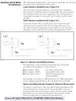
When one long continuous twisted cable is wound on a conductive drum with a relative permeability of greater than one, several things happen.
First, proximity effect. Extremely low level of course, as the conductor is easily 3 to 4 centroid spacings away from the bulk centroid of the cable. This will conspire to shift the current centroid within the two conductors, and it will result in an increase in conductor resistance as measured by an inductance meter (note, it also effectively alters the insulation conductance, or G, but a simple inductance meter is incapable of distinguishing between conductor resistance and, eddy dissipation as both are in phase with the current). This can also happen with the shield of the neighbors of the cable, but again distance rears it's ugly head.
Second, Lenz effect. Eddy currents in the conductive surface try to exclude the dipole magnetic field of the cable from the metal. This also increases the effective resistance of the cable as measured by a very good inductance meter. This ALSO decreases the per foot inductance of the cable, as the dipole field is being excluded from part of the region around the cable.
Third, if the spool has a relative permeability greater than 1, it can enhance the magnetic field a tad in the low frequency ranges, but again, it is at least 3 centroid spacings from the center of the dipole field.
Fourth, as the wire is spooled layer to layer, the twist pitch expressed as circumference angle changes as radius...in other words, neighbors on the same layer may couple a bit magnetically if the length per turn is an integral multiple of the cable twist pitch, but neighbors on previous and later layers cannot because the twist pitches are not matched, the different layers require different amounts of cable length.
Absolutely none of this invokes the solenoidal equational relationship between number of turns and inductance. None, so put that hypothesis away, it's dead.
Now, let's look at the test setup. What exactly is the AP doing? Is it measuring the phase difference between ends, or relative phase between lf and hf?
How does it respond to the termination mismatches at both ends? Remember, we are talking audio band here, and the line impedance AND propagation velocity are both frequency dependent. How does the AP respond to a transmission line delay?
A quick review:
Spooling the wire does:
1. Changes the effective per foot R and G as a consequence of proximity to a metal spool for wires in direct contact, neighbor shields, even internal copper of neighbor cables.
2. Changes the effective per foot L as a consequence of lenz effect and the spool metrics of epsilon and mu.
The wire already has non uniform prop velocity and characteristic impedance, now we toss in the changes caused by proximity to metals.. Zero distortion within the audio band for long length cables requires a delicate balance between the per foot R and G, this was worked out by those guys doing phone work many years ago.. Telographer guys. Where do you think mu metal was used?? Underwater.
So, when you push the AP "button", what exactly is it doing?
Ed, while the data is great and all, your statement that it's because the inductance rose because it was coiled?? No.
Far more interesting things are happening. Let's pursue it further..
ps. See, very simple..
jn

Remember, I hilite the discussion of effects that reach outside the cable. And I point out the verbage after the word "fourth" as the most significant for crosstalk.
Now I believe you when you mention some folks believe English is your second language as you are reaching conclusions from my posts that I don't think are there.
Ed, I copied your posts..
Why? Do it right, use the autocal function, control the test, use Ls/Rs.I await your test of inductance on a 50' coil of shielded cable.
Oh, and by the way. When you perform the autocal function, do this:
Where the two wires just go into the braid, you must short the wires right there during shorted autozero. What you are doing is telling the meter to remove the inductance from it's circuitry all the way to the short. That removes the loop you had at the meter, in the picture. For the numbers being discussed here, that little loop can be at the same level as the inductance you are trying to measure. edit:do NOT autozero the meter in Lp/Rp and then test in Ls/Rs. You MUST autozero in the mode you are using for the final test.
jn
BTW, not only did I point out the coupling mechanisms and geometrical constraints, I also provided the mechanisms whereby a shielded mike cable can interact with any metals they may lie against. This is another impact, beyond crosstalk, that can bite ya when coiling a mike cord on a conductive spool. And, as an added extra bonus, it lend's credence to your (untested) assertion that coiling a speaker wire on a conductive spool can impact the sound from the speaker.
So as you can see, we're not enemies Ed.
Last edited:
I'll show you mine, now show me yours!
Can you get a tripod for that camera? Those pics are so blurry..
You'll have to wait a while. I've two offices, and I'm at the wrong one, so can't take a pic.
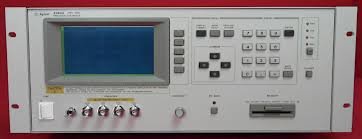
I have two HP 4284A units on the production floor, and a third one in my office that refuses to boot up. It has a 3 inch by 3 inch crt display, with 4 in line bnc's to connect the test leads. I could take a pic, but it'll have to be Monday. I'm sure it comes up in google somewhere.
I can certainly scan the cal pages if you think it might be of interest to you.
I also have another HP unit, can't recall the model number, but it has 100, 120, 1k, 10k, and 100k test frequency selections, and it's a heck of an accurate bugger when I need to measure very very small inductances. It's the one I use when I'm trying the 10 nanohenry and below stuff. The HP 4284A is great in that you can select a specific frequency to measure, not just what it decides is best.
What interests me more is the AP you have. I understand they can be very accurate, so I think part of this thread should be figuring out how to use it to discern the effects we speak of.
Have a nice weekend
edit:heres a pic from the web, not a very good one...
jn
Attachments
Last edited:
Changing things changes the sound - in the world of engineers this is regarded with great suspicion unless you have a case hardened, bullet proof, 'perfect', explanation for why it happened. And so we have the typical throwaway line that it was all in their heads, a fantasy, a delusion - the perfect 'Get out of jail free' card, effective for all occasions ... ,
, Most of us might settle (temporarily) for an interim explanation which is plausible both in terms of claimed mechanism and likely order of magnitude. We rarely get even that.fas42 said:Changing things changes the sound - in the world of engineers this is regarded with great suspicion unless you have a case hardened, bullet proof, 'perfect', explanation for why it happened.
I'll show you mine, now show me yours!
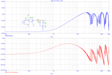
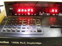
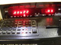
So, what has been learned here? First, posting without captions is garbage.
Second, the test mode is very important. Your initial tests using Lp/Rp gave readings that were off by three orders of magnitude. You justified those readings because of the number of turns and the solenoidal equation of inductance vs turns. At least that is now out of the way.
I note that page 3-15 of the manual for your machine states that the series mode is more appropriate for air core inductors..
It is very refreshing to see those leading zero's, with numbers far more consistent with the actual numbers expected of the cable.
Now, let's review the actual numbers being seen, and why they may or may not be accurate.
160 nH for the shorted seems ok, but can't you autocal that out? The manual says you can.
Then 9.11 uH, 9.16 uH, 6.25 uH, and 6.22 uH.
I assume one set is coiled and one uncoiled.
I did not find in your manual a discussion of Q, series resistance or capacitance issues which will impact the measurement accuracy. As I stated quite a while ago, these meters are incapable of discerning capacitance from the inductance readings. So unless you can scan across frequency and plot the resultant values, you still do not know which is the correct value. I assume the uncoiled would be the correct one, and the coiled is compromised.
Nonetheless, as you can see, the number of turns vs solenoidal inductance is totally blown outta the water. All that's left is to figure out how badly your meter reacts to capacitance.
But you're getting there. Perhaps somebody else could repeat it using a better meter, scanning across the frequency band to identify confounders that are not visible using a single frequency.
jn
Attachments
ES-
Can you be more specific about the cable? I may be able to match it and see what I see with different measurements.
West penn wire 291 in yellow as shown on the first set of pictures. But also try the two coils. Send terminated with 150 ohms.
Receive with 10 k.
I would like to address something that might make a difference with aspiring audio designers and builders.
I have noted on other threads where many schematics, both old and new, are put up proudly, as favorites. Not to dismiss any particular schematic, I would like to point out some potential compromises that many of these schematics show.
The first, with the power amp schematics is the VALUE of the output inductor added.
IF it is more than 2uH, look for trouble. YET, I see a number of schematics with 10uH. This is too much, way too much.
A second clue is how many power output devices are there for a given Wattage. IF there is only a single output pair, you are compromising peak current drive, as well as INVITING serious safe area protection triggering with real music playing at some nominally reasonable level. More output pairs give more peak current, AND a potential reduction in the protection circuitry sensitivity. This can be very important.
Look back at many of the schematics recently put up on this website, and take note.

- Status
- Not open for further replies.
- Home
- Member Areas
- The Lounge
- John Curl's Blowtorch preamplifier part II