I love that clemsen link, thank you. I'm forwarding it to one of the post docs here, he needs a transformer to get from a signal source of 50 ohms to some much higher and so far arbitrary impedance for some kind of optical crystal thingy at 50 MHz. I detailed to him how he could use a 1/4 wave transformer, length would be less than 5 feet, and we can easily create whatever impedance t-line needed for the job. Excellent, thanks again.Jneutron
Thank you for answering.
Although this discussion doesn’t fit my size, I was involved, because I have experienced myself the issue of silly cable readings with one of my LC cheap digital meters
I had to go to some equations (here is the online version Clemson Vehicular Electronics Laboratory: Transmission Line Impedance Calculator) to see what the “expected” measurement should be.
I understand that the issue of a meaningful L/C reading is equally difficult with advanced LCR measuring instruments.
See below (page 42-47, 52-58, 84, 99-115) for some very useful data and info that have to be considered when measuring L/C
http://cp.literature.agilent.com/litweb/pdf/04275-90001.pdf
George
The agilent link doesn't load, but that again I'm sure will be excellent. I use the manual with my HP 4284A, so I suspect it's much of the same thing. Those guys are 6 and 7 digit accuracy fiends...
Does your link have a theory of operation section? Or, a measurement procedures and examples section? HP goes heavily into how to prevent setup problems.
jn
Last edited:
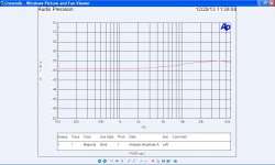
Here are the results of 200' of portable mic cable. I ran the F plots at 10mV but stepped the phase up to 10 volts as the AP seemed to lose it's grip on reality.
The most important band is around 5,000 hertz and the coiling seems to reduce the phase shift there.
Looks like something (noise) is ramdomly triggering 2pi phase wrapping. You also have pi/2 net phase with no features in the frequency plot of any significant magnitude, doesn't this bother you also.
Last edited:
The agilent link doesn't load,
jn
Mea culpa. This link will work
http://www.home.agilent.com/agilent/redirector.jspx?action=ref&cname=AGILENT_EDITORIAL&ckey=734262&lc=eng&cc=GR&nfr=-536900197.536897567.00
Does your link have a theory of operation section? Or, a measurement procedures and examples section? HP goes heavily into how to prevent setup problems.
Yes+yes+yes.
The page numbers I mentioned refer to the pdf page numbering.
Reading is instructive even for an instrument with a single decimal digit

I detailed to him how he could use a 1/4 wave transformer
I guess you will satisfy the post doc a bit more if you send him this link
Audio calculations in English - acoustics calculator convert audio formulas sound calculations microphone formula sound recording studio useful stuff free audio calculator recording studio acoustic audio engineering site map online education sound ca
There are at least two calculators he will find handy for the transformer job
Reactance calculator R L C inductance inductor capacitance capacitor frequency - sengpielaudio
Conversion of time difference and sound path distance or length millimeters time of arrival milliseconds calculate calculation delay line noise sound wave in air calculator variance ITD Haas effect duration - sengpielaudio Sengpiel Berlin (it works with speed of light too)
George
It did. Thanks.
Keeping them for myself...thanks. That way, I'll look smart to him..I guess you will satisfy the post doc a bit more if you send him this link
Audio calculations in English - acoustics calculator convert audio formulas sound calculations microphone formula sound recording studio useful stuff free audio calculator recording studio acoustic audio engineering site map online education sound ca
He's actually very good even though he's a chemistry phd (where's Sy
). A while back I gave him an iron lam toroidal core using 1 mil thick iron tape. I put 4 primary winds of 10 turns each, and gave him some transformer tutorial paperwork.. He learned it, and wound the secondary to match his needs of 1Kv and 1.5 Kw, running at 20 Khz using a bridged QSC rmx1450 (mine on loan). Some kinda plasma experiment.. Thing ran cool as a cucumber.jn
Looks like something (noise) is ramdomly triggering 2pi phase wrapping. You also have pi/2 net phase with no features in the frequency plot of any significant magnitude, doesn't this bother you also.
I showed five runs of each test. The noise bumps are quite an issue. It seems the AP is jumping phase lock. If you subtract out the bumps you get the same phase curve that has no discontinuities. So looking at those there is a small phase difference that might actually be heard.
As to no change in the FR plot for the phase change, yes I would expect -3db at 5,000 hertz for the FR plot if the losses were due to RC action.
I read this as there is very loose coupling in the coiled cable. That is to be expected as if you twist wire "A" with wire "B" about 1/2 of the time "A" will be close to the next turn of "A" and about 1/2 of the time to "B". But it won't be exactly 1/2 so there will be some net action. This of course is complicated by other factors.
So if someone else with an AP wants to run the Frequency and Phase plots, it should be interesting to compare results.
Personally I find the phase skips quite disturbing. BTY where you see a T above the plot means the AP believes there is an error.
As to no change in the FR plot for the phase change, yes I would expect -3db at 5,000 hertz for the FR plot if the losses were due to RC action.
In fact it's a nearly perfect all pass 180 degree phase transition. Is this a clue?
I read this as there is very loose coupling in the coiled cable. That is to be expected as if you twist wire "A" with wire "B" about 1/2 of the time "A" will be close to the next turn of "A" and about 1/2 of the time to "B". But it won't be exactly 1/2 so there will be some net action. This of course is complicated by other factors.
Oh stop with this "other factors" stuff..""it's like, magic, man...""
I will try to keep this explanation as simple as possible, but one paragraph in I see that I am failing miserably at that. Sorry Ed, please try to keep up..

The cable twist pitch will be uniform along it's length. It creates a helically pitched magnetic dipole field external to the cable, and it falls off as more than 1/r, r being conductor centroid spacing. Assuming 100 mils centroid spacing, half an inch away there will be no measurable field, that being the nature of helically pitched magnetic dipoles..
Given the coupling of two twisted cables, there is NO net coupling when the twist pitch is non integrally related. This is how cat5e prevents coupling.
When one long continuous twisted cable is wound on a conductive drum with a relative permeability of greater than one, several things happen.
First, proximity effect. Extremely low level of course, as the conductor is easily 3 to 4 centroid spacings away from the bulk centroid of the cable. This will conspire to shift the current centroid within the two conductors, and it will result in an increase in conductor resistance as measured by an inductance meter (note, it also effectively alters the insulation conductance, or G, but a simple inductance meter is incapable of distinguishing between conductor resistance and, eddy dissipation as both are in phase with the current). This can also happen with the shield of the neighbors of the cable, but again distance rears it's ugly head.
Second, Lenz effect. Eddy currents in the conductive surface try to exclude the dipole magnetic field of the cable from the metal. This also increases the effective resistance of the cable as measured by a very good inductance meter. This ALSO decreases the per foot inductance of the cable, as the dipole field is being excluded from part of the region around the cable.
Third, if the spool has a relative permeability greater than 1, it can enhance the magnetic field a tad in the low frequency ranges, but again, it is at least 3 centroid spacings from the center of the dipole field.
Fourth, as the wire is spooled layer to layer, the twist pitch expressed as circumference angle changes as radius...in other words, neighbors on the same layer may couple a bit magnetically if the length per turn is an integral multiple of the cable twist pitch, but neighbors on previous and later layers cannot because the twist pitches are not matched, the different layers require different amounts of cable length.
Absolutely none of this invokes the solenoidal equational relationship between number of turns and inductance. None, so put that hypothesis away, it's dead.
Now, let's look at the test setup. What exactly is the AP doing? Is it measuring the phase difference between ends, or relative phase between lf and hf?
How does it respond to the termination mismatches at both ends? Remember, we are talking audio band here, and the line impedance AND propagation velocity are both frequency dependent. How does the AP respond to a transmission line delay?
A quick review:
Spooling the wire does:
1. Changes the effective per foot R and G as a consequence of proximity to a metal spool for wires in direct contact, neighbor shields, even internal copper of neighbor cables.
2. Changes the effective per foot L as a consequence of lenz effect and the spool metrics of epsilon and mu.
The wire already has non uniform prop velocity and characteristic impedance, now we toss in the changes caused by proximity to metals.. Zero distortion within the audio band for long length cables requires a delicate balance between the per foot R and G, this was worked out by those guys doing phone work many years ago.. Telographer guys. Where do you think mu metal was used?? Underwater.
So, when you push the AP "button", what exactly is it doing?
Ed, while the data is great and all, your statement that it's because the inductance rose because it was coiled?? No.
Far more interesting things are happening. Let's pursue it further..
ps. See, very simple..
jn
Last edited:
Now that this thread has turned into a 'lounge act' rather than an engineering thread, I might put some perspective on this latest debate.
I don't have a 'dog in this fight'. I could care less whether a coil of 'shielded' audio cable measures or behaves differently when it is coiled or drawn out. However, it has been noted by Ed Simon that he has actually seen measurements obscured or fouled up by leaving the audio cable coiled. This is what we call a PRACTICAL problem, rather than a theoretical one, and the EXACT reasons for the problem are secondary to the fact that a problem exists.
Now, JN apparently thinks more 'ideally' and based on his education there should be NO problem. So he called Ed on his opinion.
Ed did a simple measurement and found a small difference with only a short length of wire. Every aspect of his measurement has been attacked, including his test equipment, his ability to do an accurate measurement, and secondary problems that might make his test equipment measure inaccurately. Yet, there was a difference measured, AND THAT IS THE POINT!
Practical engineers like Ed and me care more about differences than just why these differences exist. Others who are buffered from these practical audio situations that we are exposed to, might not easily accept that these differences can really exist. But does it help to attack Ed's statement, when he has noted this particular difference in the field, and not in the classroom?
Last edited:
In fact it's a nearly perfect all pass 180 degree phase transition. Is this a clue?
Scott,
The parameter we are looking at is called crosstalk. I placed two 50' coils of microphone wire near each other. The send coil was sourced from 50 ohms and terminated in 150 ohms. The receive coil had a 10,000 ohm termination and fed the input of the AP. The results are shown.
What to me was interesting in the phase plots was the "noise" jumps even at a signal level of 10 volts and that they mostly appeared at the same spot on the frequency sweeps. I suspect there is a very interesting issue here we are missing.
Just for informational purposes, is the AP stimulus swept, impulse, MLS, or...?
The swept signal mode.
Attachments
Last edited:
Scott,
The parameter we are looking at is called crosstalk. I placed two 50' coils of microphone wire near each other. The send coil was sourced from 50 ohms and terminated in 150 ohms. The receive coil had a 10,000 ohm termination and fed the input of the AP. The results are shown.
What to me was interesting in the phase plots was the "noise" jumps even at a signal level of 10 volts and that they mostly appeared at the same spot on the frequency sweeps. I suspect there is a very interesting issue here we are missing.
The swept signal mode.
OK now I'm really confused.
No, the problem is twofold.However, it has been noted by Ed Simon that he has actually seen measurements obscured or fouled up by leaving the audio cable coiled. This is what we call a PRACTICAL problem, rather than a theoretical one, and the EXACT reasons for the problem are secondary to the fact that a problem exists.
The first problem is that a terribly incorrect attribution was given to an observation. Solenoidal inductance is NOT the reason for any measured difference (NOTE, even an INCORRECT measurement which was cherry picked because the correct measurement did not show the effect).
This is exactly the same thing that happened to you when you did all your work on measuring IC cables. You found that the test results relied heavily on how you cleaned the contacts. Eventually, it became obvious that it was a ground loop effect, lack of current path control which confounded your measurements.
The second, and more dangerous problem IMHO:
It is not acceptable to validate preconceived notions by using bad test methodology, and choosing bad methodology because it provided the desired results.
The PRACTICAL problem here is, the test was messed up as a consequence of the nature of the equipment and the obscure workings of inductance.
A cherry picked, incorrect and inaccurate test result was described as being a consequence of solenoidal inductance. Obviously, that is incorrect.
Now, JN apparently thinks more 'ideally' and based on his education there should be NO problem.
Bzzzzt. Wrong guess Hans...you wanna go to double jeopardy where the dollars can really go up??
I speak from 30 years of experience, the last 20 in an environment which is very high end. I measure inductances from 680 henries down to 250 picohenries, a span of 12 orders of magnitude, with errors 4 orders of magnitude below this particular discussion.
I have the luxury of my education, in that I understand the physics of the problem and can explain it. But I measure it as part of my living.
Ed himself stated that he chose the Lp/Rp model because it showed more delta than the proper test. That is significant.Ed did a simple measurement and found a small difference with only a short length of wire. Every aspect of his measurement has been attacked, including his test equipment, his ability to do an accurate measurement, and secondary problems that might make his test equipment measure inaccurately.
Engineering is not about making up reasons for measured differences. You were bit by that with your making up contact non linearities, VDH got bit by making up grain boundary reasonings, in both cases the test methodology was NOT up to par with what was being measured. edit: It is important to make a distinction here..both you and VDH were really pushing new limits with your test equipment, and that is VERY commendable. Your test actually helped spur me to learn more about ground loop theory and practice.Yet, there was a difference measured, AND THAT IS THE POINT!
Practical engineers like Ed and me care more about differences than just why these differences exist.
Ed did the same with the wrong selection of test, the lack of control of the measurement, and the erroneous insistence that solenoidal inductance was the cause.
You cannot hide behind the mantra of "practical engineer" so that you can make up wildly inaccurate physics explanations. That's how high end audio gets caught up in all the garbage explanations, like grain boundary, skin effect on line cords, the sound of wire insulation or color..
But does it help to attack Ed's statement, when he has noted this particular difference in the field, and not in the classroom?
My field of engineering application and my field of engineering theory is in the discipline we are discussing. I'm a magnet guy. And I am comfortable as well in the classroom, where I have to detail what I do for a living.
jn
Last edited:
Scott,
The parameter we are looking at is called crosstalk. I placed two 50' coils of microphone wire near each other. The send coil was sourced from 50 ohms and terminated in 150 ohms. The receive coil had a 10,000 ohm termination and fed the input of the AP. The results are shown.
So, now we've changed the subject?? Crosstalk of two balanced shielded cables is not the same as solenoidal inductance. I guess we can assume you gave up on that, and are now going after crosstalk...excellent, as that is exactly in line with my previous discussion about lenz, eddy, coupling, and dispersion. It requires field spillage, which is crosstalk..
What is the field termination impedance for a balanced mike?
What is the shield coverage for the cables you just tested?
Where is the schematic? Did you drive balanced and receive balanced?
When confronted with test results which seem inconsistent, you have to approach it in a logical fashion. You're jumping about in your presentation.
Now, is this statement about the previous phase plots?
It was indeed weird that it happened at the exact same spot. You should have run a sine into it and scoped the output, then sweep it through the point where it goes nuts. edit: you must keep the exact same drive and termination impedance however, as it may be important to keep the reflection coefficients at both ends the exact same as the AP does.What to me was interesting in the phase plots was the "noise" jumps even at a signal level of 10 volts and that they mostly appeared at the same spot on the frequency sweeps. I suspect there is a very interesting issue here we are missing.
The phase droop upper band is the most interesting, disregarding the huge jumps, because the amplitude doesn't change much. What you need to do is a variable frequency TDR. I don't suppose you have a modified RF bridge, do you? An alternate approach would be a low inductance CVR and the drive end ground, then scope the line phase.
If you peruse Cyril Bateman's article on this, it may make more sense to you.
jn
ps... Ed, in case you haven't figured it out yet, I commend and think very highly of you on your questions, your tests, your willingness to bring up various notions as possible explanations. I find discussion/debate with you very refreshing, and prefer this to a world of no discussion. Thank you.
Last edited:
Here are the results
Ed
Is it possible to describe in detail the test set-up and the conditions that the 5 sweeps in the phase plots mean to represent?
Now that this thread has turned into a 'lounge act' rather than an engineering thread
Mr Curl
Engineers do sit in a bar stool and have an interesting conversation about technical issues (e.g. the kick-back observed due to women inductive nature)
George
In order to measure a phenomenon you have to be fairly close to understanding it; you need a good theory. Some 'practical' engineers don't always realise this. Without a good theory all you have is a number on a meter, or a graph on a screen: in themselves these are data, not information. It is very easy to measure something different from what you intend to measure or think you are measuring.
In order to measure a phenomenon you have to be fairly close to understanding it; you need a good theory. Some 'practical' engineers don't always realise this. Without a good theory all you have is a number on a meter, or a graph on a screen: in themselves these are data, not information. It is very easy to measure something different from what you intend to measure or think you are measuring.
I thought we didn't agree much??
jn
Mr Curl
Engineers do sit in a bar stool and have an interesting conversation about technical issues (e.g. the kick-back observed due to women inductive nature)
George
Me personally, I sit ON a bar stool.. until about the 4th drink...then, yes, I too am IN the bar stool. But luckily, it has my name engraved on the back of it, as I have purchased it many times over.
However, as DF96 said...""In order to measure a phenomenon you have to be fairly close to understanding it; you need a good theory. Some 'practical' engineers don't always realise this.""
Which of course means, we engineers will be unable to measure a woman...
jn
Last edited:
- Status
- Not open for further replies.
- Home
- Member Areas
- The Lounge
- John Curl's Blowtorch preamplifier part II