For a standart line stage yes.
Sorry I didn't explain it correct. I mean using a line stage with low gain / buffer stage with gain around 1 or up to 6dB (or a passive unit like a TVC / autoformer).
That's the sort of line stage which is more appropriate in this century and is increasingly more common (sometimes no line stage at all, hard to do better than that!). It's not difficult to build in a few extra dB of gain into a phono stage to try to have average levels match modern sources, but one must be aware that there's no hard limit to the potential output- a tick, pop, or mistrack has the potential to cause clipping somewhere along the chain.
Opinions about gain are numerous. However Joao got the gist of the problem, which is an upsetting change in level between sources. Unfortunately, attenuators cause more noise, and a need for higher intrinsic preamp gain. This would be a problem with the CTC Blowtorch, no problem with the Parasound JC-2.
What I'm wondering about is that present designed line stages have large gain, for example 20dB but, the phono stage don't have more or less than 46dB.
Why not lay out the line stage as buffer / impedance converter with lower gain or zero gain and increase the gain of the phono stage?
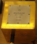
I wonder why nobody sells audiophile chassis in plain machined gold.
... mmh, maybe due to Class A temp operating point , especially with toobz ... it would melt ?

True for both aluminum and steel chassis? Would copper work? Silver for the loonies that crave precious metals? (Finally some intrinsic value for an audio product.)
Silver is best, and it gives that rich sound ta boot..
 .
.Copper is second.
Aluminum third
Gold further down.
1- As long it is not magnetic and conduct electricity
Any chassis with permeability greater than 1 will attempt to channel magnetic flux, so any external field caused by the transformer wil be "gathered up" and directed by a a magnetic material. If this "re-direction" is in the correct orientation, it can generate time varying electric potentials.Toroids are best at field containment simplly by the geometry of the core. Sharp corners, rectangular geometries will tend to have non-uniform magnetic field line densities, so will tend to allow some field to be less contained where the geometry is varying.
By inserting a conductive shield, the shield will generate internal currents which will try to exclude the magnetic fields, this is the Lenz effect, or rather, Lenz's law. This can be spotted from the line cord by simply measuring the inductance of the transformer unloaded, and then put the conductive shield in. If the shield is restricting any field, the system inductance will lower. By doing an inductive sweep from say 20 hz out to about half a meg and plotting the L vs freq, you can see the effect the conductive shield has on the leakage field of the xfmr.
Ed, you've run unplugged, powered no load, powered load...try one with the grounding conductor only but the xfmr unpowered.
Oh, btw. in a standard bridge supply set, the line cord has odd harmonics, the secondary has evens. This is of interest if you wish to distinguish between parasitics due to the winding couplings to the core, or if it's the core field itself doing the coupling.
jn
audiophile chassis in plain machined gold.
They do, it's called an Ingot amp, single requirement is to drill & thread some holes.
(duh, no one likes my patent approved wording)
Attachments
Last edited:
It is funny, in a perverted sort of way. I use thick aluminum and I am attacked for wasting money and material. I already knew that copper or silver would actually work BETTER, but we could not afford to use it. Yet you joke that a real hi end product would use such exotic materials freely.
It is though you do not truly appreciate the cost of gold and silver in audio equipment.
Even a little bit, where it might actually do some good, is expensive.
Yet many here work in labs and factories that must have hundreds of thousands or millions of dollars invested in equipment and materials, and hardly think twice of how you could 'lower' the cost of your own design efforts. You just pass it on to whoever, usually the government.
Hi end, to be acceptable to a certain class of every wealthy individuals, has to be made to a certain standard of quality, in form and finish. These can be the targeted customers, and therefore they must be accommodated. This was true, as far back as Mark Levinson's early designs, in the case of the Japanese buyers.
While there are notable exceptions, you get what it costs to make and a little left over as profit, like any other enterprise, when you buy relatively expensive audio equipment.
some simple things can help in certain places for certain issues:
What else can be done?
View attachment 335733
Thx-RNMarsh
Clever,
I sometimes use a series pass semiconducter just after the rectifier. It is set so that it conducts until the input voltage rises to about 70% of the peak voltage. That way you get some regulation, but you also are not squashing the top of the sine wave. It helps power factor, cancels some harmonics and can be used to derive multiple voltages from a single transformer.
Scott,
Just for you http://www.jensen-transformers.com/as/as019.pdf This started life with an NE5534 and seems some one just plugged in a newer chip. However when I built one it didn't work correctly. So I'll leave it open as to how many folks can suggest how to improve this circuit.
ES
Oh, btw. in a standard bridge supply set, the line cord has odd harmonics, the secondary has evens. This is of interest if you wish to distinguish between parasitics due to the winding couplings to the core, or if it's the core field itself doing the coupling.
jn
jn, I would suggest to halt contributing, else Ed will be short of fingers, counting the variables affecting his FFTs for his article.
Ed
May I give you some more troubles?
Don’t count on “nominal” load for each trafo when you check for leaking fields. These fields ramp-up as soon as the waveform starts showing flat tops/bottoms.
There are really not many trafos I have checked which manage decent waveforms.
Start checking the waveforms with trafos unloaded. You’ll probably give-up soon.
Then feed the primaries from a Variac. Adjust variac for an output ½ of main’s voltage and start increasing it while monitoring the waveform and leaking fields of the trafo under test.
I bet a bottle of Ouzo that in most cases – and this doesn’t have to do with the type of trafo- reaching an 80-85% of mains voltage is the upper limit for nice waveforms and the rest.
Only then check effects of loading for each type of construction, operating each trafo at this upper input voltage.
George
in a perverted sort of way.
Only gold plated, weigh about 15lb each, had one in my hand shortly after they were released.(didn't make it to the front door)
http://www.diyaudio.com/forums/soli...mplifier-i-have-ever-heard-6.html#post2326337
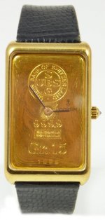
In the '50s and '60s, Swiss watches in the US often had gold plated cases, the inferior bodies were manufactured in America for tax reasons.
e.g. Rolex.
Attachments
Last edited:
some simple things can help in certain places for certain issues:
What else can be done?
View attachment 335733
Thx-RNMarsh
Wouldn't you reverse bias the elco every half cycle this way?
It is funny, in a perverted sort of way. I use thick aluminum and I am attacked for wasting money and material.
…
Twisting words and meanings in a perverted sort of way. Just enough for to convince yourself that in this site you are attacked instead of being praised (or “believed”).
George
Clever,
Scott,
Just for you http://www.jensen-transformers.com/as/as019.pdf This started life with an NE5534 and seems some one just plugged in a newer chip. However when I built one it didn't work correctly. So I'll leave it open as to how many folks can suggest how to improve this circuit.
ES
I really don't understand why you would need a DC servo (even two) in this transformer coupled setup. You can null any DC offset using pins on the AD797.
Scott,
Just for you http://www.jensen-transformers.com/as/as019.pdf This started life with an NE5534 and seems some one just plugged in a newer chip. However when I built one it didn't work correctly. So I'll leave it open as to how many folks can suggest how to improve this circuit.
ES
Elaborate on didn't work correctly. I helped Mitch Cotter with a similar problem (if it's what I think). You need a turn on catcher for the Ib comp network (the one the user can't see).
Gpapag, you don't need to be insulting to me specifically. I expressed my criticism in general, from my point of view.
I do my best to put up with, as well as understand any criticism put up here.
You made me ring the bell.
When it comes to thick aluminium for front panels, there are many out there (cosmetics and “feel”).
The possible technical reasons for mm of aluminium in home audio gear have been discussed here for good and in a technical manner.
The “aviation grade’ and the tens cm thickness were criticized.
RF sections in avionics (antennas input) and broadcasting (“ball receivers” within repeater stations) have to be housed into chambers and channels machined into billets of aluminium. But there, the RF fields for which the electronics are to be shielded from, measure in kV/m
George
Mr. Cheesy Weezy in the little Squeezy,
might as well take the opportunity to inquire what your stance is on DC servoing ?
Me? I'm neutral.
Attachments

some simple things can help in certain places for certain issues:
What else can be done?
View attachment 335733
Thx-RNMarsh
Well, you could flip it around if you're on 120vac mains with a dual 120vac primaries. In either event, you'd be in 'violation' of Menno Vanderveen's US patent # 6087822. This is used in the Torus conditioners from Bryston.
It worked quite well on the primaries of an overspecified r-core powering a dac.
Last edited:
But there, the RF fields for which the electronics are to be shielded from, measure in kV/m
George
kV/m????
Ah, ok...you're talking about standby mode...
jn
- Status
- Not open for further replies.
- Home
- Member Areas
- The Lounge
- John Curl's Blowtorch preamplifier part II