The fact that a digital source can deliver 2V RMS does not mean that it should routinely do this. The average output level of a well-recorded and well-engineered digital source will be much smaller than this, so there is some headroom for peaks.nowadays we have analog and digfital as emanicipated sources in audio systems. But compared to phono a digital source deliver higher signal output (≥ 2Vrms) to the line stage. What about designing the phono stages with more gain to have equal signal levels?
"The beast with the 1000 triodes"
Don't tell the Mastah I favor the Philly lighthouse version.
Don't tell the Mastah I favor the Philly lighthouse version.
?????
Philly -> Lampegat -> Guido
(the Pass periphery sometimes has this "Renfield" je-ne-sais-quoi flavor. Renfield @ Bram Stoker's Dracula (1992) - YouTube )
(the Pass periphery sometimes has this "Renfield" je-ne-sais-quoi flavor. Renfield @ Bram Stoker's Dracula (1992) - YouTube )
Back to phono. Over the decades, we have increased the phono output somewhat to match modern (digital) input levels. However, it is difficult without having a very high output, before clipping.
Exactly. And I'm amused when people talk about stupendous overload margins on phono preamps, and don't follow the signal and its effects thereafter. How many have power amps capable of hundreds of volts of output swing, and after that, how many loudspeakers will accept such voltages?
It must be remembered that the PHONO STAGE is placed BEFORE the volume control. This means that lot of input voltage to the preamp is thrown away by having some range on the volume control. It is often a matter of CONVENIENCE that people demand the same sort of levels as digital based components tend to give (on average) that causes people to demand more gain from a phono stage. IF they would just turn up the volume pot a bit, there would be no need for any extra gain.
Dick,
Five of the six transformers are UL listed.
here are the leakage readings in uA. The order is Normal AC line to core, Normal AC line to Center Tap, Hot-Neutral reversed to core, Reversed to CT.
1 R-core, coil is vertical to chassis bottom. Core reading is at chassis point of attachment. Shield is connected to chassis and safety ground, (Open at AC receptacle.) 19.3, 3.3, 18.9, 2.7
2 Toroid, coil is vertical to chassis bottom. Core reading is at chassis point of attachment. No shield. 8.3, 7.3, 9.6, 17.1
3 Signal 14A-20-24, Coil is horizontal to chassis and perpendicular to the long axis. Core is read with sharp robe to core. Has extra plastic insulation to meet world standards. 1.6, .9, 2.0, 1.2
4 Signal PC-24-1000, coil is vertical to chassis bottom. 2.8, 5.3, 3.0, 1.3
5 Signal DST-6-24 almost the same as #3 except slightly different core size and no extra plastic. 1.9, 1.2, 2.4, 1.4
6 Signal LP-24-1000, Coil is horizontal to chassis and perpendicular to the long axis. Core is read with sharp robe to core. This is a flatpack style with dual bobbins each bobbin has a primary and secondary. 2.3, 1.1, 2.3, 1.2
ES
It must be remembered that the PHONO STAGE is placed BEFORE the volume control. This means that lot of input voltage to the preamp is thrown away by having some range on the volume control. It is often a matter of CONVENIENCE that people demand the same sort of levels as digital based components tend to give (on average) that causes people to demand more gain from a phono stage. IF they would just turn up the volume pot a bit, there would be no need for any extra gain.
Another aberration I noticed, when designing some equipment to please certain Japanese, was that they desired very high sensitivity for their audio components. In the case of one powered speaker, 50mV rms was supposed to be enough for full output. Apparently, as much as I could divine, it was important that the volume control, already audio taper, only needed to be advanced to about 8 o'clock or so for normal listening levels.
But the customer is never wrong, even when they may not always be right.
Does the leakage increase with increased load on the transformer?
-RNM
Good question, I'll run that tomorrow. My expectation is no, but we'll see.
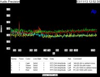
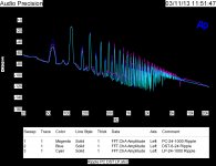
Attached are the noise isolation and ripple. The noise is shown as a baseline with the transformer hooked up as a center tap to two diodes. The filter is 2200 uF and the load is 50 ohms. The noise is measured across the filter capacitor as is the ripple.
My noise source is a small relay connected as a buzzer. The relay coil is coupled via a single 1nF 2000V cap to the AC hot side. The rest of the path is through the diode bridge feeding the relay and the stepdown transformer.
Attachments
Good question, I'll run that tomorrow. My expectation is no, but we'll see.
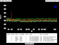
Attached are the noise isolation and ripple. The noise is shown as a baseline with the transformer hooked up as a center tap to two diodes. The filter is 2200 uF and the load is 50 ohms. The noise is measured across the filter capacitor as is the ripple.
My noise source is a small relay connected as a buzzer. The relay coil is coupled via a single 1nF 2000V cap to the AC hot side. The rest of the path is through the diode bridge feeding the relay and the stepdown transformer.
Am also meaning induced current levels in the metal ground attached to xfmr. -RNM
Good question, I'll run that tomorrow. My expectation is no, but we'll see.
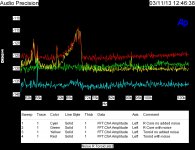
Attached are the noise isolation and ripple. The noise is shown as a baseline with the transformer hooked up as a center tap to two diodes. The filter is 2200 uF and the load is 50 ohms. The noise is measured across the filter capacitor as is the ripple.
My noise source is a small relay connected as a buzzer. The relay coil is coupled via a single 1nF 2000V cap to the AC hot side. The rest of the path is through the diode bridge feeding the relay and the stepdown transformer.
Could you point me to the post with your circuit? I can't seem to find it. Thanks
Mr Russell.
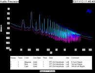
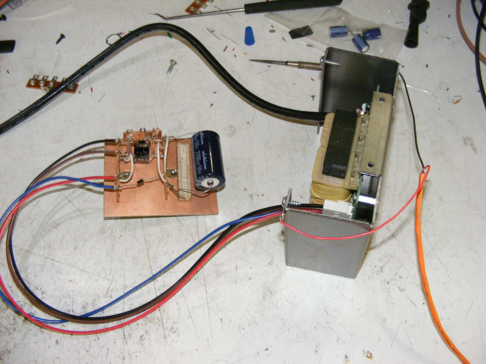
"It is two diodes going to a 50 ohm resistor filtered with a 2200 uF capacitor. In the ground leg is a .1 ohm resistor that has a transformer load on the secondary by 72 ohms"
http://www.diyaudio.com/forums/atta...ch-preamplifier-part-ii-2013_0309misc0003.jpg
http://www.diyaudio.com/forums/anal...rch-preamplifier-part-ii-731.html#post3402589
It must be remembered that the PHONO STAGE is placed BEFORE the volume control. This means that lot of input voltage to the preamp is thrown away by having some range on the volume control. It is often a matter of CONVENIENCE that people demand the same sort of levels as digital based components tend to give (on average) that causes people to demand more gain from a phono stage. IF they would just turn up the volume pot a bit, there would be no need for any extra gain.
Chain of thought was to have no difference between the aources and provide the system from loud levels when people (forget to decrease the volume)before switching to louder digital front end. So a better solution would be to implement an attenuator at each inputs.
Mr Russell.
"It is two diodes going to a 50 ohm resistor filtered with a 2200 uF capacitor. In the ground leg is a .1 ohm resistor that has a transformer load on the secondary by 72 ohms"
http://www.diyaudio.com/forums/atta...ch-preamplifier-part-ii-2013_0309misc0003.jpg
http://www.diyaudio.com/forums/anal...rch-preamplifier-part-ii-731.html#post3402589
Ah! A picture is worth a 1000 words
")
Ah! A picture is worth a 1000 words
A schematic is worth more.
Chain of thought was to have no difference between the aources and provide the system from loud levels when people (forget to decrease the volume)before switching to louder digital front end. So a better solution would be to implement an attenuator at each inputs.
If you design the phono stage for circa 150mV out, assuming it feeds into a standard 16dB gain line stage, you should be about right. No point in designing the phono output stage for much more than that IMO.
BTW for normal listening levels, my volume control is between 11 o'clock (comfortably loud) and say 2:30 (wifey complaining bitterly).
A picture is worth a 1000 words
Asseblief, vir die audio wildebees van die Natal, ek denk es tog geen moeite nie.
- Status
- Not open for further replies.
- Home
- Member Areas
- The Lounge
- John Curl's Blowtorch preamplifier part II