I am listening to my brand new v 1.6, a few hours old, through my crappy TEAC cd player and an Akitika pre, nice kit. It sounds like it's not there, but performs a bunch of functions well. PR-101 Stereo Preamplifier
Jason / 6L6,
Perhaps people are missing this incredible new guide, because the Kit item in the store links to the older 1.5 version of the guides. I think that clicking on the "all new detailed guide..." link should go to the new 1.6 guide now, instead of the 1.5
Rafa.
True in my case. Once I got to the 1.6 guide and found the wiring diagram, it was off to the races, I could proceed with confidence.
Build guide is, on the whole, most excellent. Many thanks to all who have participated in its composition.
Success! 
ACA V1.6 #1 is completed. No smoke on power up; Both LED's illuminated, made music from both channels in stereo mode, and through both channels in mono mode.
Bench check through a test driver only so far.
Don't have a balanced source to check that function.
Bias set to 11.93V & 11.89V with no problem.
What a rush!
I felt like Gene Wilder (Dr. Fronkensteen) in "Young Frankenstien"
"IT'S AL-I-I-I-Vuh!"
Now on to ACA V1.6 #2, Omega Super 3XRS speakers arrive tomorrow, new Schiit Guingnir DAC is about broken in....
In the process of changing my M.O. from med power A/B amplification and 2-way med efficiency speakers to the above.
Last edited:
Left channel out after initially OK
I finished my ACA 1.6 a few weeks ago and it sounded great. Now the left channel sound is gone. The LED light is shining, but no sound. Using the voltage checklist recently posted (Thank You!) I find these disparities:
Pot -- Bias at Q1 is 2.33v and is largely unaffected by rotating the pot 'knob' (increases at maximum to 2.7v); This pot initially biased at 12v no problem.
Q1 at D is 22v (should be 12); Q1 at S is 4.36v (should be 0)
Q2 at D is 17.3v (should be 24); Q2 at S is 13.45 (should be 12.9)
R10 on Q4 side is 0.68v (should be 3.5-4.1v)
R15 off Q3b is 13.2 (should be 12.6) and then across the resistor drops to 12.67v (should be 12v)
Other voltage checks are within range.
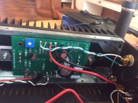
Many thanks to anyone who can offer some suggestions. I can't see anything obvious as far as solder issues or wiring, but am posting a photo of the problem PCB below.
Jim
I finished my ACA 1.6 a few weeks ago and it sounded great. Now the left channel sound is gone. The LED light is shining, but no sound. Using the voltage checklist recently posted (Thank You!) I find these disparities:
Pot -- Bias at Q1 is 2.33v and is largely unaffected by rotating the pot 'knob' (increases at maximum to 2.7v); This pot initially biased at 12v no problem.
Q1 at D is 22v (should be 12); Q1 at S is 4.36v (should be 0)
Q2 at D is 17.3v (should be 24); Q2 at S is 13.45 (should be 12.9)
R10 on Q4 side is 0.68v (should be 3.5-4.1v)
R15 off Q3b is 13.2 (should be 12.6) and then across the resistor drops to 12.67v (should be 12v)
Other voltage checks are within range.
Many thanks to anyone who can offer some suggestions. I can't see anything obvious as far as solder issues or wiring, but am posting a photo of the problem PCB below.
Jim
Attachments
Jim, I'd suggest to start with removing pcb and very carefully examine it for cold or missing joints, re-solder any suspects and if nothing obvious found check components values and placement.
I've had similar problem - one channel biased as expected, the other one did not react to the trim pot at all and had around 20V on Q1 at D. Took off the pcb and immediately saw that I completely forgot to solder center leg on the trim pot. Once soldered it biased just fine so both channels now up and running. BTW, in the excitement of catching my error I forgot to tighten up screw on one of the transistors during reassembly which inevitably would cause failure over time. Fortunately I've noticed this while setting bias")
I've had similar problem - one channel biased as expected, the other one did not react to the trim pot at all and had around 20V on Q1 at D. Took off the pcb and immediately saw that I completely forgot to solder center leg on the trim pot. Once soldered it biased just fine so both channels now up and running. BTW, in the excitement of catching my error I forgot to tighten up screw on one of the transistors during reassembly which inevitably would cause failure over time. Fortunately I've noticed this while setting bias
Jim, the led is connected through a single resistor to the main voltage and then ground. So having it light up means really only that voltage is going into the PCB, little more.I finished my ACA 1.6 a few weeks ago and it sounded great. Now the left channel sound is gone. The LED light is shining, but no sound...
My troubleshooting skills here are going to be really a starting point, only a few 'baby steps', but could be worth a shot:
- Have you made sure it is not a problem with the source? Have you swapped the right and left RCA inputs. If the sound 'flips' to the other speaker? That would suggest a failure on the source of your music.
- Have you made sure its not a problem with the speakers? Have you swapped the right and left speaker wires? If the same speaker remains playing, then the problem is the speakers and not the amp.
If both those tests remain consistent that you get only sound from the same PCB, try to check:
- if there is no wire o resistor leg that may be protruding too far back on the PCB and touching the heatsink. That could cause some of your behaviors.
- if by chance one of the MOSFETs is not electrically coupled to the heatsink. The thermal screen may have been 'cut' by too much pressure on the MOSFET's screw. This is easiest done by checking if there is continuity between the MOSFET's middle pins and the heatsink when the PSU is disconnected. If there is continuity, then there may be a short to the heatsink.
Other than that, I am of little help, but others will surely come to the rescue with more ideas to try.
Best regards,
Rafa.
I finished my ACA 1.6 a few weeks ago and it sounded great. Now the left channel sound is gone. The LED light is shining, but no sound. Using the voltage checklist recently posted (Thank You!) I find these disparities:
Pot -- Bias at Q1 is 2.33v and is largely unaffected by rotating the pot 'knob' (increases at maximum to 2.7v); This pot initially biased at 12v no problem.
Q1 at D is 22v (should be 12); Q1 at S is 4.36v (should be 0)
Q2 at D is 17.3v (should be 24); Q2 at S is 13.45 (should be 12.9)
R10 on Q4 side is 0.68v (should be 3.5-4.1v)
R15 off Q3b is 13.2 (should be 12.6) and then across the resistor drops to 12.67v (should be 12v)
Other voltage checks are within range...
Jim,
First thing is as Rafa says then check for poor solder joints, look at the white wire at the RCA connector for example, it looks poor from the picture.
Second can you re check all the readings? There are some discrepancies in the results you posted.
I:'Bias' is measured at Q1-D - you have 2 results ''2.33v and 22v''.
II: R15 'bottom' is joined to Q1-D by the PWB track so should read the same, but you have 12.67v? (Does that alter if you turn the 'bias' pot? If so set it to 12 volts.)
Other odd readings are Q1-S and Q2-D. These are the negative and positive supplies directly to the boards, so should read 0v and 24v unless you have poor connections in the wiring.
Out of interest, where did you put your Negative meter lead for the measurements?
So best to re do the checks and also compare both boards results. If you did not before, use the bare copper buss as your negative meter lead location. Let us know what you get please.
Alan
note to 6L6
for parallel operation , you don't need Y cable , just U shortie showed in holes 2 & 3 of input XLR
well , if one does have proper dia solid core to make U shortie
I usually don't have that ....... even if I'm doing that for different purposes
Just to make sure I've got this right for parallel input, mono block mode.
("Parallel Input" mode listed on "V1.6 Operation Modes" table)
Back panels on my ACA's are wired for front switch power, back switch for stereo or mono modes.
1. Short across XLR 2 & 3 (or use appropriate Y cable), to place an RCA input in parallel to both PCB's within each ACA.
2. One channel's RCA input to either RCA jack (or Y cable) on each ACA.
3. One speaker to the Black output terminals on each ACA.
4. Back panel switch down (stereo/contacts open).
Last edited:
After removing the problem PCB, resoldered some funky looking connections. Now all seems well. Thanks for the help.
Jim
Great news, thanks for letting us know.
Alan
Just to make sure I've got this right for parallel input, mono block mode.
("Parallel Input" mode listed on "V1.6 Operation Modes" table)
Back panels on my ACA's are wired for front switch power, back switch for stereo or mono modes.
1. Short across XLR 2 & 3 (or use appropriate Y cable), to place an RCA input in parallel to both PCB's within each ACA.
2. One channel's RCA input to either RCA jack (or Y cable) on each ACA.
3. One speaker to the Black output terminals on each ACA.
4. Back panel switch down (stereo/contacts open).
Nearly but not quite.
1: Correct.
2: Correct.
3: No, you have to 'parallel' the outputs together too. You have to join the two Black sockets together - either internally or externally with a speaker jumper lead. (The Red ones are already connected together in steps 36 - 39 of the build guide.) Then use one Red and one Black. It does not matter which of course.
4: Correct, down contacts open. Personally I would remove the resistor that goes to the switch so you cannot accidentally select 'bridge' mode. That would also allow the switch to be used to join the two black speaker sockets together...
Alan
Last edited:
Nearly but not quite.
1: Correct.
2: Correct.
3: No, you have to 'parallel' the outputs too. You have to join the two Black sockets together. (The Red ones are already connected together in steps 36 - 39 of the build guide.)
4: Correct, down contacts open. Personally I would remove the resistor that goes to the switch so you cannot accidentally select 'bridge' mode.
Alan
3. I suspected it would be so, but decided to just ask and be sure.
4. Easy enough, a good idea.
Thanks from an "electronics challenged" electrician.
Right channel not working anymore
Hi,
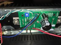
I've completed my 1st ACA about 2 weeks ago and it worked fine. I pulled it out today to try the unbalanced bridged mono setup (I have a second ACA that works fine) and no sound came out. I configured back to stereo and now the right channel is dead (the left channel is working). I measured voltages and everything is according to spec. I've also compared the internal wiring against the other ACA and could not find any difference. Any ideas where to look or what to check / measure?
Best
Michael
Hi,
I've completed my 1st ACA about 2 weeks ago and it worked fine. I pulled it out today to try the unbalanced bridged mono setup (I have a second ACA that works fine) and no sound came out. I configured back to stereo and now the right channel is dead (the left channel is working). I measured voltages and everything is according to spec. I've also compared the internal wiring against the other ACA and could not find any difference. Any ideas where to look or what to check / measure?
Best
Michael
Attachments
zimmer64 If your voltages are correct and match the working side, then check your input and output connections next.
See on the other thread #5958
If the reading is Much higher or open circuit on either, you have a poor connection.
Alan
See on the other thread #5958
.... with no power supply, speakers or input attached, check the resistance between the red and black speaker sockets. Use the 20k ohms range on your meter. The reading should be 0.5k to 1k ohms. The reading will slowly rise as C1 charges from the battery in your meter, this is correct, so ''it takes a few seconds'' to get to the proper reading. You are making sure you have not shorted the output wires / terminals somewhere.
The input socket test is the same, you are confirming there is no short across the input. This time you select the 2 meg ohm range on the meter and measure from the outer of the RCA socket to the inner ring. A good reading is about 50k ohms. (Again the reading will rise slowly as the capacitor is charged so takes a few seconds.)
If the reading is Much higher or open circuit on either, you have a poor connection.
Alan
zimmer64 If your voltages are correct and match the working side, then check your input and output connections next.
See on the other thread #5958
If the reading is Much higher or open circuit on either, you have a poor connection.
Alan
Hi,
I have 0.99k ohms between the speaker posts and 50k ohms on the RCA's on both side. So that seems to be ok. Where to go next?
Thank you for your help.
Michael
... I have 0.99k ohms between the speaker posts and 50k ohms on the RCA's on both side. So that seems to be ok. Where to go next?
Difficult to say. If the voltages are OK and the input and outputs are OK, it should be working. The picture is difficult to see, but I hoped R11 was not soldered in correctly - next to C3 under the blue wire.
I assume you have tried swapping the input source and speakers left to right? It would not be the first time a faulty input or speaker lead was to blame.
That said, re-check the voltages, using the working side as reference, note any differences.
Then it will be remove the faulty board and check for dry or missed solder joints, wire strands etc.
Alan
Thank you Alan. Yes, I have swapped all input and output cables. As it worked fine for a week or so, I guess there is a wonky solder joint somewhere. What strikes me though is, that voltages look fine on both channels, which feel not logical to me. I guess I will put the board and re-flow all joints just to sure.
zimmer64 Michael,
If you are feeling brave...
you might try a power on test with a speaker connected and an input of some sort playing just to the faulty channel. With a wooden coffer stirrer or BIC biro tube, nothing metal, gently prod / tap each component and solder joint in turn. It just might locate a poor connection. Sure to be something simple (I hope).
Alan
- Home
- The diyAudio Store
- Amp Camp Amp Kit 1.6/1.8