I have tried to do the resistance checks from the build guide for v1.6 step 55.
My numbers are off and are more or less the same on both modules.
Can I due the measurements with the boards completely stuffed and all wire connections made?
This is what I have measured:
R9.S should be 1K but is 0.5K
R10.G should be 335K but is 332K
Q4.D should be 1K but is 0.5K
Q1.S should be 0 and is 0
Q1.D should be 5.2K but is 5.53K
R15.B should be 5.8K but is 5.21K
R15.E should be 5.2K but is 4.52K
R5.C should be 10.9K but is 10.4K
Q2.G should be 11K but is 10.55K
Q2.D should be 1K but is 0.5K
Q2.S should be 5.2K but is 4.52
It is like there is missing 0.5K somewhere, or...???
Is this enough to point at what is wrong or should I continue with the voltage checks?
(Measuring is not nearly as fun ad soldering….)
Normally you can't do component test "in-circuit" but it makes sense that the resistance you measure is less than expected as current finds other paths than only through the component under test. The meter calculates the resistance from the applied voltage and the current (R = U/I).
Ok.....but measurements form Gnd to different points on the board makes sense if you measure DC voltages around to check that all DC levels are correct. It requires that the amp has power.
Measuring of resistance through semiconductors can vary a lot. It also depends on what current the meter uses…...so I would say that your numbers looks ok.
Measuring of resistance through semiconductors can vary a lot. It also depends on what current the meter uses…...so I would say that your numbers looks ok.
Trying to measure circuit resistance parameters 'in circuit' will never give consistent and reliable results I'm afraid.
Even the meter range used (or automatically selected if its an auto ranging DVM) can substantially affect readings, as does the meter test lead polarity (because the test voltage forward biases semiconductor junctions in circuit).
Try as I suggested earlier and confirm the DC bias current operating point is correct and then do a quick check on the gain using a known (measured) signal voltage.
I have tried to do the resistance checks from the build guide for v1.6 step 55.
My numbers are off and are more or less the same on both modules.
Can I due the measurements with the boards completely stuffed and all wire connections made?
This is what I have measured:...
... It is like there is missing 0.5K somewhere, or...???
Is this enough to point at what is wrong or should I continue with the voltage checks?
(Measuring is not nearly as fun ad soldering….)
damkel, everyone, the idea of the 'Resistance checks' is to make sure there are no obvious shorts or open circuits or resistors in the wrong places. It is not a supposed to be an exact value for each location, just an initial indication. Your figures are fine in that respect, you have not lost 0.5k - simply differences in meters and capacitors charging etc. and you have not misunderstood the guide.
Yes it and the Voltage checks are for fully stuffed and wired boards. (Some of the test points are difficult to mark on a picture of the completed board.)
The troubleshooting step is 'work in progress', and we should make these things a little clearer, as well as improve the 'acceptable range' figures in the future, but can only do that with more input, the sample is small at the moment. Thanks.
damkel, what it does tell us is that there are no short or open circuit faults on the boards, and both are the same.
Please make sure your input and outputs are not shorted, next, as I suggested in post #5934. (Your red to black speaker readings will likely be in the 0.5k range following from the previous readings.) Then the voltage and test tone checks.
Alan
Last edited:
I added Nover 10000uf 50v C1 caps for more warmth and bass on my ACA #1. What are the sonic differences between the former ACA #1 and the new 2018 ACA?
I suspect very little. The 1.6 version has a little tiny bit more power from the 24 volt supply, the feedback resistor R12 is 39k in place of the 68k and R15 (2.2k) has been added across Q3 b/e junction. Everything else is the same I think?
Alan
Last edited:
Hi damkel - The boards and wiring look good at first glance. You can adjust the bias, so another positive.
What are you using as a source? They do not play loud with inputs like phones etc.
Now check the resistance between the red and black output terminals. It should be near 1k ohms on the 20k range (it takes a few seconds to get there). If it is very low you have a short somewhere. Do the same for the input socket, that should be about 50k on the 2 meg range, again it takes a few seconds. A low reading again indicates a short. Then do the test Meper tells you to, measure the ac volts on the output terminal with a loud source (or 1kHz test tone if possible).
Sorry for being a noob...
Does this mean that I feed the ACA with a 20k Hz tone and then there should be 1k ohm between the two output terminals?
The next I am sorry I do not understand:
"Do the same for the input socket, that should be about 50k on the 2 meg range, again it takes a few seconds."
Sorry for being a noob...
Does this mean that I feed the ACA with a 20k Hz tone and then there should be 1k ohm between the two output terminals?
Not a problem,
No it means with no power supply, speakers or input attached, check the resistance between the red and black speaker sockets. Use the 20k ohms range on your meter. The reading should be 0.5k to 1k ohms. The reading will slowly rise as C1 charges from the battery in your meter, this is correct, so ''it takes a few seconds'' to get to the proper reading. You are making sure you have not shorted the output wires / terminals somewhere.
The next I am sorry I do not understand:
"Do the same for the input socket, that should be about 50k on the 2 meg range, again it takes a few seconds."
The input socket test is the same, you are confirming there is no short across the input. This time you select the 2 meg ohm range on the meter and measure from the outer of the RCA socket to the inner ring. A good reading is about 50k ohms. (Again the reading will rise slowly as the capacitor is charged so takes a few seconds.)
Once you know these are good, then check and confirm the voltages are OK.
Alan
PS
The test tone is more complicated, it involves playing a sound [a tone] at a known ac amplitude [voltage] into the input and measuring the voltage you see on the speaker terminals. It should be about 1 to 3. So 1 volt ac in for 3 volts ac out. One thing at a time?
Last edited:
Alan, thank you for your reply.
It turned out not to be nearly as complicated as I thought and now I know it makes good sense... and I do feel a bit stupid")
I have measured as told and got 0.92K on the speaker connectors. Same value on both channels.
On the inputs I got exactly 50K again same on both boards.
I am starting to suspect that maybe nothing is wrong, maybe I don't have a source with enough gain or the impedance is to high.
How do I find out if my sources har a low output impedance?
What would be a good source for testing just to find out if it is OK? Would the signal for a PC soundcard be usable?
Or, should it be a CD player? (which I don't have anymore but I guess I could buy a used one cheap…)
Tomorrow I will try to measure voltage as Meeper suggested.
Have I understood correct that there is no reason to do the voltage checks from the troubleshooting guide?
Thank you all for your patience!!!
It turned out not to be nearly as complicated as I thought and now I know it makes good sense... and I do feel a bit stupid
I have measured as told and got 0.92K on the speaker connectors. Same value on both channels.
On the inputs I got exactly 50K again same on both boards.
I am starting to suspect that maybe nothing is wrong, maybe I don't have a source with enough gain or the impedance is to high.
How do I find out if my sources har a low output impedance?
What would be a good source for testing just to find out if it is OK? Would the signal for a PC soundcard be usable?
Or, should it be a CD player? (which I don't have anymore but I guess I could buy a used one cheap…)
Tomorrow I will try to measure voltage as Meeper suggested.
Have I understood correct that there is no reason to do the voltage checks from the troubleshooting guide?
Thank you all for your patience!!!
I am starting to suspect that maybe nothing is wrong, maybe I don't have a source with enough gain or the impedance is to high.
This comment resonated with me given my own experience.
I had each (of 2) ACA hooked up as an SE stereo amp and had it working fine.
Then I relocated them and connected them as monoblocks to my Freya pre via balanced interconnects and then ... nothing.
I double checked all the ins and outs and started scratching my head. Then I put my ear close to the speakers and sure enough, sound was getting through. So, then I just cranked up the volume on the Pre- ... all sorted.
The Freya comes with a 128 step, 0.625dB/step, stepped attenuator and it can take a while for the level to rise. I simply didn't have the gain from the Pre working hard enough. It was previously connected to an AB class with (comparatively) bucket loads of power and gain, so it was just a case of setting up for the new conditions. Had me worried for a little bit there but all good in the end.
I just have to remember to turn it down if/when the ACAs get changed out in future.
A very rough method to get a high enough signal is to connect a RCA cable to the amp and then on the other end of the RCA cable just touch the center pin only of the RCA connector. This should give a loud 50 Hz distorted sound from the speakers. But it should only be done a fraction of a sec. It is normally something you do only by mistake but if this will not bring the ACA to life…..then something it probably wrong with it. Many will probably not recommend such a test......but doing it by mistake I have never seen any damage……..yet…….but I am chocked every time…...by the loud sound...…..it will learn you how "hum" sounds...….
I have measured as told and got 0.92K on the speaker connectors. Same value on both channels.
On the inputs I got exactly 50K again same on both boards.
I am starting to suspect that maybe nothing is wrong, maybe I don't have a source with enough gain or the impedance is to high.
Tomorrow I will try to measure voltage as Meeper suggested.
Have I understood correct that there is no reason to do the voltage checks from the troubleshooting guide?
Well every thing so far looks good. You could be right, and you just need more gain. A number of builders have found they need a pre-amplifier with some gain to drive the ACAs with.
It would be very helpful for you (and other builders) if you checked what the voltages were.
The picture in the guide is for the 1.6 version with a 24 volt supply. You have the 1.5 version with the 19 volt supply, so the numbers will be different. Where it has 24 volts yours should be 19 volts. Where it has 12 volts (bias) you will read 10 volts (bias) on Q1 D and R15 bottom. And so on.
Alan
Hey all. Finished my ACA 1.6 this evening and happy to say it didn’t explode. In fact it sounds great and wow those blue leds are bright. I set the bias with it on for only 5 minutes or so, it sounds like I should let it warmup for 30 then check bias again? Should I be playing audio while it warms up or just let it go alone?
Also, the whole unit is supposed to be hot, right? Not just the heat sinks, but also the front panel, the top panel, Anywhere I can touch is pretty warm. I’m hoping that is normal?
Also, the whole unit is supposed to be hot, right? Not just the heat sinks, but also the front panel, the top panel, Anywhere I can touch is pretty warm. I’m hoping that is normal?
All over hot is normal. The midpoint voltage (what everyone seems to call bias for some reason ) should be set with no signal applied. It doesn't matter whether speakers are connected or not.
The set value shouldn't drift by much, but setting it when its all warmed up is the logical thing to do.
) should be set with no signal applied. It doesn't matter whether speakers are connected or not. The set value shouldn't drift by much, but setting it when its all warmed up is the logical thing to do.
damkel
Here is a way to test your ACA is amplifying correctly. I just tried it on mine and this is what I did.
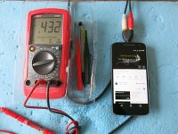
Used my mobile phone and went to this site for the 1 kilo Hertz test tone, it is a bit louder than some. YouTube
I turned my phone's volume to maximum and measured the AC voltage at the head phone socket playing the tone. Mine is 0.43 volts AC. Yours might be more or less, just note what it is.
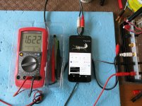
Then I plugged the phone into my ACA and measured the output at the speaker terminals. (No speakers connected.) I get 1.622 volts AC.
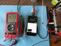
If I connect my speaker (8 ohms) and measure I get 1.57 volts AC.
Again yours might be different just note it.
So on my amplifier for an input of 0.43v ac I get 1.57v ac out.
3.6 times amplification and you should get something similar if all is well.
Hope that helps.
Here is a way to test your ACA is amplifying correctly. I just tried it on mine and this is what I did.
Used my mobile phone and went to this site for the 1 kilo Hertz test tone, it is a bit louder than some. YouTube
I turned my phone's volume to maximum and measured the AC voltage at the head phone socket playing the tone. Mine is 0.43 volts AC. Yours might be more or less, just note what it is.
Then I plugged the phone into my ACA and measured the output at the speaker terminals. (No speakers connected.) I get 1.622 volts AC.
If I connect my speaker (8 ohms) and measure I get 1.57 volts AC.
Again yours might be different just note it.
So on my amplifier for an input of 0.43v ac I get 1.57v ac out.
3.6 times amplification and you should get something similar if all is well.
Hope that helps.
Attachments
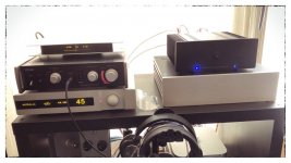
...wow those blue leds are bright.
Congratulations on getting it right first time.

If you don't like the bright LED's, you can swap them out for diffused LED's as well as higher value resistors.
Because I didn't feel like removing R13, I just added an additional resistor in series on one of the LED legs. IIRC it was something like 20K, which dims the LED suitably, but it's still bright enough for daytime visibility.
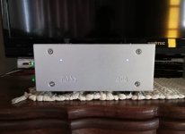
The picture doesn't show the soft blue color properly, but believe me it's a pleasing soft blue - not harsh on the eyes at all.
Attachments
Last edited:
- Home
- Amplifiers
- Pass Labs
- Amp Camp Amp - ACA