Hi guys.
I guess I should check in here more often haha.
A few thoughts, Iand, a properly done measurement trumps a computer prediction every time, those measurements are what one uses to tweak the computer model so that it predicts more like what you measure.
Computer models in acoustics are rarely exact, at best they come close which makes them a powerful tool for those who make sawdust.
For a good chunk of my life, I would have given my arm for David’s horn program for example.
But, if you want to KNOW the actual excursion, that requires you observe it directly at a known level and frequency.
You want to know how much port loss there is at a given power level, measure the change in response with a given box / port / drive level etc.
You have to measure, models only include things to a given depth, for example you can represent an inductor as an L, or you can represent it as an L in series with an R paralleled by a small C which is in series with an R, and so on and on.
In the case you are investigating, in particular you should actually build / measure a high power ported box and tweak your computer model accordingly. These systems depend on having low losses and as the level increases and / or frequency decreases, so do the losses and the greater the impact that has.
You ask me to prove things, to design a 320L Tapped horn box for you, I would say step back and think about it.
Proof is a proper measurement; a proper execution is one that works “like intended”.
I occasionally have to build 3 or 4 different prototypes if the first ones measurements weren’t close enough.
A computer model has to be interpreted into an air and wood shape and that is not always a simple or obvious thing either.
Also, while I am a DIY’r and grew up doing that, I have kids and am trying to make a living doing this so there is a limit to how far I can go so far as “showing secret sauce” (if and when it exists) as you say. I try to make the simplest things which do the job and in general I don’t try to hide what I’m doing hence the white paper explains the nub of how it works but doesn’t show how to design one.
Actually you guys have made very fast progress figuring these out with only a few clues, which is pretty cool (thinking back to how long it took to figure out how to make one that could be a product).
Lastly, keep in mind that our products at work are mostly used in commercial sound, in that area the weight and cost of the speakers and power amps are also usually significant concerns.
Best,
Tom
Tapped horn modeling
Ian:
Would you, please, post the Hornresp Input Parameter windows for your designs? It would make communication a lot easier and clearer. E.g.: In Post #1298 you tell us: "S1=285 (3:1 CR) L=20/280/20cm (all exponential) S3=2400", and I'm almost certain that's supposed to be S4=2400; or, in my last post you were immediately able to see that I used "Ang=0.5xPi" (fumble fingers, and I'm just not interested in using a tapped horn for outdoor concerts). This would also remove any doubt as to the driver parameters used (e.g: data sheet impedance v. measured impedance).
It is my belief, that the simulation tools (that have been made available for no cost and practically no outside contribution except by the original programers) are quite adequate to, quote: "come up with decent tapped horn designs (Post #1298)". This has been proven by quite a number of builders. If I understand you correctly, you are trying to compare data derived from your Hornresp model with data you extracted from Tom Danley's publications, and it looks as if you have gone about as far as one can considering the guesses and vagaries involved, as always, the devil seems to be in the details.
I agree, there is room for improvement in the simulation tools, and I am thankful for the continuing effort being put forward. You may want to try to extend your modeling efforts to AkAbak, and develop a more detailed model including exact driver front chamber dimensions, throat area, individual waveguide sections and individual corners, exact S3 area (minus the area displaced by the driver), exact mouth area with respective end correction and not to forget the resonators and their acoustic and physical contributions, and the impact of acoustic treatment; and then it would be just great if you would share the new found model and knowledge in this thread.
Regards,
P.S.: I just run a spell check on the above and WordPerfect’s spell checker wanted to replace AkAbak with Icebox, so much for that.
")
Ian:
Would you, please, post the Hornresp Input Parameter windows for your designs? It would make communication a lot easier and clearer. E.g.: In Post #1298 you tell us: "S1=285 (3:1 CR) L=20/280/20cm (all exponential) S3=2400", and I'm almost certain that's supposed to be S4=2400; or, in my last post you were immediately able to see that I used "Ang=0.5xPi" (fumble fingers, and I'm just not interested in using a tapped horn for outdoor concerts). This would also remove any doubt as to the driver parameters used (e.g: data sheet impedance v. measured impedance).
It is my belief, that the simulation tools (that have been made available for no cost and practically no outside contribution except by the original programers) are quite adequate to, quote: "come up with decent tapped horn designs (Post #1298)". This has been proven by quite a number of builders. If I understand you correctly, you are trying to compare data derived from your Hornresp model with data you extracted from Tom Danley's publications, and it looks as if you have gone about as far as one can considering the guesses and vagaries involved, as always, the devil seems to be in the details.
I agree, there is room for improvement in the simulation tools, and I am thankful for the continuing effort being put forward. You may want to try to extend your modeling efforts to AkAbak, and develop a more detailed model including exact driver front chamber dimensions, throat area, individual waveguide sections and individual corners, exact S3 area (minus the area displaced by the driver), exact mouth area with respective end correction and not to forget the resonators and their acoustic and physical contributions, and the impact of acoustic treatment; and then it would be just great if you would share the new found model and knowledge in this thread.
Regards,
P.S.: I just run a spell check on the above and WordPerfect’s spell checker wanted to replace AkAbak with Icebox, so much for that.
Re: AkAbaK vs. Hornresp.
After reading subsequent posts I realise I should have made clear that the models were not identical (as David stated, anything other than identical output would be unexpected otherwise). So my post title was misleading. "A model that happens to be in Hornresp vs. a model, with some extra bits, in AkAbaK" would have been more accurate.
The point was that separately developed models were within 20% in SPL and excursion over a wide frequency band. This band includes regions where the rear (and front for that matter) load on the driver is high impedance and others where it is low impedance. I would be surprised to see reality much different over the *whole* band (unless the driver parameters are wrong), but I'd not be surprised at all to see differences at certain frequencies. Time will tell (laser vibrometer available in a couple of months for some tests on a model speaker, I think).
Ken
kstrain said:
The results are not identical but the excursion and response are both within 20% (and are both larger in Hornresp so the SPL for a given excursion is rather similar).
After reading subsequent posts I realise I should have made clear that the models were not identical (as David stated, anything other than identical output would be unexpected otherwise). So my post title was misleading. "A model that happens to be in Hornresp vs. a model, with some extra bits, in AkAbaK" would have been more accurate.
The point was that separately developed models were within 20% in SPL and excursion over a wide frequency band. This band includes regions where the rear (and front for that matter) load on the driver is high impedance and others where it is low impedance. I would be surprised to see reality much different over the *whole* band (unless the driver parameters are wrong), but I'd not be surprised at all to see differences at certain frequencies. Time will tell (laser vibrometer available in a couple of months for some tests on a model speaker, I think).
Ken
iand said:After all, I expect the same basic equations which relate impedance, radiation resistance, excursion and SPL are used in all cases (is this true?)
Hi Ian,
Just confirming that Hornresp uses a universal simulation model, applicable to any loudspeaker system.
Kind regards,
David
Tom Danley said:Hi guys.
I guess I should check in here more often haha.
A few thoughts, Iand, a properly done measurement trumps a computer prediction every time, those measurements are what one uses to tweak the computer model so that it predicts more like what you measure.
Computer models in acoustics are rarely exact, at best they come close which makes them a powerful tool for those who make sawdust.
For a good chunk of my life, I would have given my arm for David’s horn program for example.
But, if you want to KNOW the actual excursion, that requires you observe it directly at a known level and frequency.
You want to know how much port loss there is at a given power level, measure the change in response with a given box / port / drive level etc.
You have to measure, models only include things to a given depth, for example you can represent an inductor as an L, or you can represent it as an L in series with an R paralleled by a small C which is in series with an R, and so on and on.
In the case you are investigating, in particular you should actually build / measure a high power ported box and tweak your computer model accordingly. These systems depend on having low losses and as the level increases and / or frequency decreases, so do the losses and the greater the impact that has.
You ask me to prove things, to design a 320L Tapped horn box for you, I would say step back and think about it.
Proof is a proper measurement; a proper execution is one that works “like intended”.
I occasionally have to build 3 or 4 different prototypes if the first ones measurements weren’t close enough.
A computer model has to be interpreted into an air and wood shape and that is not always a simple or obvious thing either.
Also, while I am a DIY’r and grew up doing that, I have kids and am trying to make a living doing this so there is a limit to how far I can go so far as “showing secret sauce” (if and when it exists) as you say. I try to make the simplest things which do the job and in general I don’t try to hide what I’m doing hence the white paper explains the nub of how it works but doesn’t show how to design one.
Actually you guys have made very fast progress figuring these out with only a few clues, which is pretty cool (thinking back to how long it took to figure out how to make one that could be a product).
Lastly, keep in mind that our products at work are mostly used in commercial sound, in that area the weight and cost of the speakers and power amps are also usually significant concerns.
Best,
Tom
Hi Tom
I absolutely agree that an accurate real life measurement is the best thing, since it includes effects which might not be simulated such as nonlinearity. But you still need a starting point for a design (derived from simulation) which is close enough that you make the right basic design choices in the first place...
I wasn't asking or expecting you to give up the precise details of what you do inside your boxes (because it's your living!), I was asking if you could shed any light on the fact that your measured (or simulated using your own program?) excursion and SPL are considerably different to the best that it seems possible to do in Hornresp.
As was said in another post, the predicted dips and peaks won't agree exactly with the real thing, and they move around anyway with small tweaks to the design. So I doubt that the design I came up with is exactly the same as the TH-115, but any small detail differences can't explain the average measured SPL over the band being 3dB higher than simulated, or the peak excursion being 40% lower.
Errors this big are very likely to mean that people make wrong design decisions -- for example, deciding to use a reflex box because the tapped horn doesn't seem to give higher SPL or lower excursion (!!!), or to try and find a driver for a tapped horn with much higher Xmax (price, weight) than is actually needed (like the TC PA-5100 -- there are much cheaper drivers with similar BL/Mmd but smaller Xmax).
So it would be really helpful if you could give a few hints on how different the simulations are to real life, for example:
-- is the design I came up with close enough to the TH-115 that the SPL results should be *broadly* similar -- in other words, Hornresp consistently predicts SPL 3dB lower than a real-life tapped horn?
-- does a real-life tapped horn seem to have excursion about 60% or so of that predicted in Hornresp?
If we can establish rules-of-thumb like this (e.g. simulate in Hoirnresp, add 3dB to SPL and multiply excursion by 0.6) then it will enable people to take a much better shot at home-brewed tapped horns (not commercial obviously!).
Or if there's some missing factor in the simulations that can easily be fixed (and that you could tell us about) then maybe David could put this into Hornresp to improve the accuracy of the simulations.
Of course I realise size and weight matter for PA, that's exactly why I want the highest SPL I can get out of a given sized box (all our PA has to go in one Transit van) -- and it now *does* seem that the best answer is likely to be a tapped horn after all...
Cheers
Ian
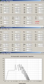
P.S. Hornresp input parameters attached as requested
Attachments
B&C 15TBX100 designs
Hi Ian,
Thanks for posting the input parameters for your model. I'll attach what I came up with for the TH-115 for comparison, it is also based on a guess at the internals.
I'll also attach input and SPL for a B&C 15TBX100 design that trades off SPL for low frequency extension and box size.
Hi Ian,
Thanks for posting the input parameters for your model. I'll attach what I came up with for the TH-115 for comparison, it is also based on a guess at the internals.
I'll also attach input and SPL for a B&C 15TBX100 design that trades off SPL for low frequency extension and box size.
Attachments
Re: B&C 15TBX100 designs
Hi Oliver
Thanks, I'll try your "TH-115" design tonight -- am I right in guessing that the average efficiency across the band is still close to what I got?
One way to resolve the possible "real-vs-simulated" discrepancy would be for Tom to simulate the exact TH-115 design in Hornresp (or AkAbak) and post just the results (SPL, excursion) for comparison with measurements -- this way we could see what the difference is, without Tom giving anything away about what his "104dB/W secret sauce" is -- how about it, Tom?
The second result is interesting -- you seem to be using the tapped horn to *reduce* the driver sensitivity from its direct-radiator value in order to get extended LF response, which is certainly a novel use of a horn, tapped or not
Cheers
Ian
P.S. I'm not trying to get Tom to reveal *how* he gets such good results, just establish whether the differences are because he's so much better at tapped horn design than we are (I should hope so, but 3dB and 60% excursion is a hell of a lot!) or because the simulations are wrong -- or a bit of both...
tb46 said:Hi Ian,
Thanks for posting the input parameters for your model. I'll attach what I came up with for the TH-115 for comparison, it is also based on a guess at the internals.
I'll also attach input and SPL for a B&C 15TBX100 design that trades off SPL for low frequency extension and box size.
Hi Oliver
Thanks, I'll try your "TH-115" design tonight -- am I right in guessing that the average efficiency across the band is still close to what I got?
One way to resolve the possible "real-vs-simulated" discrepancy would be for Tom to simulate the exact TH-115 design in Hornresp (or AkAbak) and post just the results (SPL, excursion) for comparison with measurements -- this way we could see what the difference is, without Tom giving anything away about what his "104dB/W secret sauce" is -- how about it, Tom?
The second result is interesting -- you seem to be using the tapped horn to *reduce* the driver sensitivity from its direct-radiator value in order to get extended LF response, which is certainly a novel use of a horn, tapped or not
Cheers
Ian
P.S. I'm not trying to get Tom to reveal *how* he gets such good results, just establish whether the differences are because he's so much better at tapped horn design than we are (I should hope so, but 3dB and 60% excursion is a hell of a lot!) or because the simulations are wrong -- or a bit of both...
Interesting new driver for tapped horn
Having been looking for something which might be better than the 15TBX100, I found that BMS released this since last time I looked:
http://www.bmspro.info/index.php?show=item&usbid=10282&id=5065912
http://tinyurl.com/2nf2tw
Details are sketchy so far, but going by the press releases it looks like a pretty damn impressive driver which could be a killer in a tapped horn:
-- carbon fibre cone (nice and strong for high CR), triple demodulating rings
-- 38mm coil in 12mm gap (15TBX100 has 25mm coil in 12mm gap)
-- Xmax 13mm linear, 16mm mathematical (15TBX100 is 6.5mm/9mm)
-- 1200W AES -- should be OK with 2.5kW amp...
If this simulates well, just think what the *real* performance could be...
Cheers
Ian
TH-115 guess models
Ian: You are correct, there is little difference between those two TH-115 models. Some of the real life differences may result from all the tight corners and bends that are not modeled in Hornresp. I'll try to model the new BMS driver tonight(?). Well, back to work.
Ian: You are correct, there is little difference between those two TH-115 models. Some of the real life differences may result from all the tight corners and bends that are not modeled in Hornresp. I'll try to model the new BMS driver tonight(?). Well, back to work.
I get it!
G'day all
Iand said>P.S. I'm not trying to get Tom to reveal *how* he gets such good results, just establish whether the differences are because he's so much better at tapped horn design than we are (I should hope so, but 3dB and 60% excursion is a hell of a lot!) or because the simulations are wrong -- or a bit of both...
We have all been looking in the wrong place for the Tapped Horns hidden advantage.
This came to me while lying in bed at 2:00 this morning (as I am often inclined to do when faced with a challenge).
A loudspeaker radiating into half space has an output that decreases at -6dB with every doubling of distance. With a vented box, the origin is the driver or the port, depending on the freq the box is being driven at. Now a front loaded horn does the same thing, but the origin is still the driver, not the mouth of the horn. That means if you took a measurement at 10M out from a 4M long horn and compared it with a measurement 10M out from a vented box, the results would be very different, even if the horn output matched the VB output at 1M. I've measured this effect with front loaded horns and would have to assume it holds in a tapped horn. Tom measures his speakers at 10M for a VERY GOOD REASON. He could argue, and I'd have to agree, it more closely matches real life use. It accounts for the excellent output and efficiency seen in all the tapped horns that have been discussed here.
Ian, you are right in that a Tapped Horn has no advantage at one meter from the mouth when compared to a well designed vented box. As the distance increases, the advantage increases.
The plot thickens.
Cheers
William Cowan
Re: I get it!
Hi William
I fear you must have eaten too much cheese before bedtime...
It doesn't matter what's inside the box, fall-off of SPL with distance only depends on the radiating area of the sound source.
I'm sure others (Tom, David) will confirm this -- it sounds like a great idea, but it just ain't so :-(
Cheers
Ian
cowanaudio said:G'day all
Iand said>P.S. I'm not trying to get Tom to reveal *how* he gets such good results, just establish whether the differences are because he's so much better at tapped horn design than we are (I should hope so, but 3dB and 60% excursion is a hell of a lot!) or because the simulations are wrong -- or a bit of both...
We have all been looking in the wrong place for the Tapped Horns hidden advantage.
This came to me while lying in bed at 2:00 this morning (as I am often inclined to do when faced with a challenge).
A loudspeaker radiating into half space has an output that decreases at -6dB with every doubling of distance. With a vented box, the origin is the driver or the port, depending on the freq the box is being driven at. Now a front loaded horn does the same thing, but the origin is still the driver, not the mouth of the horn. That means if you took a measurement at 10M out from a 4M long horn and compared it with a measurement 10M out from a vented box, the results would be very different, even if the horn output matched the VB output at 1M. I've measured this effect with front loaded horns and would have to assume it holds in a tapped horn. Tom measures his speakers at 10M for a VERY GOOD REASON. He could argue, and I'd have to agree, it more closely matches real life use. It accounts for the excellent output and efficiency seen in all the tapped horns that have been discussed here.
Ian, you are right in that a Tapped Horn has no advantage at one meter from the mouth when compared to a well designed vented box. As the distance increases, the advantage increases.
The plot thickens.
Cheers
William Cowan
Hi William
I fear you must have eaten too much cheese before bedtime...
It doesn't matter what's inside the box, fall-off of SPL with distance only depends on the radiating area of the sound source.
I'm sure others (Tom, David) will confirm this -- it sounds like a great idea, but it just ain't so :-(
Cheers
Ian
Re: I get it!
An interesting idea, but it does not seem correct - at least if you mean that the effect applies the "long way round" to the rear of the driver.
For the large wavelengths and small front horn dimensions we have in mind it must be very nearly correct to consider the source of the radiation as the sum of the waves from front and rear at a point just inside the mouth (the horn is too small to be much of a horn). Then the fall-off of radiation out into free space does not depend much on the details of what went on behind - in particular not the extra ~4m of path to the rear of the driver. (Of course the frequency response depends on what goes on behind as that determines how rear and front waves add.)
I'm not denying that in the near field of a large-mouthed horn the radiation intensity will fall off more slowly than inverse square, that is OK. But I don't see that applying to a TH (beyond small effect from the short and relatively small front horn).
Am I missing something?
Anyway my room is only 8m long and not at all like free space at 30 Hz, so I'll never find out by experiment.
Ken
cowanaudio said:G'day all
<snip>
I've measured this effect with front loaded horns and would have to assume it holds in a tapped horn.
An interesting idea, but it does not seem correct - at least if you mean that the effect applies the "long way round" to the rear of the driver.
For the large wavelengths and small front horn dimensions we have in mind it must be very nearly correct to consider the source of the radiation as the sum of the waves from front and rear at a point just inside the mouth (the horn is too small to be much of a horn). Then the fall-off of radiation out into free space does not depend much on the details of what went on behind - in particular not the extra ~4m of path to the rear of the driver. (Of course the frequency response depends on what goes on behind as that determines how rear and front waves add.)
I'm not denying that in the near field of a large-mouthed horn the radiation intensity will fall off more slowly than inverse square, that is OK. But I don't see that applying to a TH (beyond small effect from the short and relatively small front horn).
Am I missing something?
Anyway my room is only 8m long and not at all like free space at 30 Hz, so I'll never find out by experiment.
Ken
Re: TH-115 guess models
Tom's pointed out on several occasions that the exact shape of the horn and bends makes very little difference at low frequencies -- once by approximating an exponential horn out of stepped tubes (same response as a smooth expansion), once by building a Servodrive Basstech 7 with beautifully rounded bends (slightly higher cutoff than a "normal" one because of lost volume, otherwise the same).
The BMS driver response is pretty close to the B&C, except the ripple (for exactly the same horn) is a little higher. Put an extra 5mH in series and it's dead flat at 100dB/W from 40Hz-110Hz, -10dB at 30Hz, excursion (according to Hornresp) is 15mm at 1200W input.
If the real vs. measured excursion difference is the same as Tom calculates for the 15TBX100, the 15N850 should handle 3300W (instead of 1200W) before running out of Xmax...
Cheers
Ian
tb46 said:Ian: You are correct, there is little difference between those two TH-115 models. Some of the real life differences may result from all the tight corners and bends that are not modeled in Hornresp. I'll try to model the new BMS driver tonight(?). Well, back to work.
Tom's pointed out on several occasions that the exact shape of the horn and bends makes very little difference at low frequencies -- once by approximating an exponential horn out of stepped tubes (same response as a smooth expansion), once by building a Servodrive Basstech 7 with beautifully rounded bends (slightly higher cutoff than a "normal" one because of lost volume, otherwise the same).
The BMS driver response is pretty close to the B&C, except the ripple (for exactly the same horn) is a little higher. Put an extra 5mH in series and it's dead flat at 100dB/W from 40Hz-110Hz, -10dB at 30Hz, excursion (according to Hornresp) is 15mm at 1200W input.
If the real vs. measured excursion difference is the same as Tom calculates for the 15TBX100, the 15N850 should handle 3300W (instead of 1200W) before running out of Xmax...
Cheers
Ian
TH-115 guess models
Hi Ian,
Post #1313, quote: "Tom's pointed out on several occasions that the exact shape of the horn and bends makes very little difference at low frequencies ..."
When you compare the response of an existing horn with sharp corner with the same horn with corners rounded you are not doing the same as comparing an idealized horn model of a straight horn without bends with the output of an actual horn with a lot of intricate bends. Between corrections for the length of the bends and the mouth end correction we may well be looking at a substantial difference in length. I think that's one of the reasons why Tom Danley keeps on making the point about building and measuring. Dr. Edgar made some remarks in his Monolith Horn paper (http://www.volvotreter.de/dl-section.htm) as to the effect of corners and horn modeling that are interesting, and apply not only to high frequencies.
Post #1313, quote: "The BMS driver response is pretty close to the B&C, except the ripple (for exactly the same horn) is a little higher...."
You are correct, the BMS-15N850 models just like the B&C-15TBX100, nice for PA/Band use. Just don't hookit up to your portable generator.
Hi Ian,
Post #1313, quote: "Tom's pointed out on several occasions that the exact shape of the horn and bends makes very little difference at low frequencies ..."
When you compare the response of an existing horn with sharp corner with the same horn with corners rounded you are not doing the same as comparing an idealized horn model of a straight horn without bends with the output of an actual horn with a lot of intricate bends. Between corrections for the length of the bends and the mouth end correction we may well be looking at a substantial difference in length. I think that's one of the reasons why Tom Danley keeps on making the point about building and measuring. Dr. Edgar made some remarks in his Monolith Horn paper (http://www.volvotreter.de/dl-section.htm) as to the effect of corners and horn modeling that are interesting, and apply not only to high frequencies.
Post #1313, quote: "The BMS driver response is pretty close to the B&C, except the ripple (for exactly the same horn) is a little higher...."
You are correct, the BMS-15N850 models just like the B&C-15TBX100, nice for PA/Band use. Just don't hookit up to your portable generator
.G'day again Ian
I think there's a bit more to it than just cheese. I have measured this effect with a front loaded bass horn I built, outside, and have reason to believe it is at least partly true with a tapped horn. My 30Hz tapped horn is at a friends house at the moment, I'll drag it outside for a measurement session when I get it back. I've only measured it inside to date.
One way of looking at the problem is to recognise that the reduction in SPL with distance is directly related to the expansion of the area of the wavefront on the surface of a sphere into which a point source radiates. Each doubling of this distance increases the area four times. In the case of a bass horn, the expansion of this wavefront did not start at the mouth, it actually started many meters back at the driver. The driver is generating a great deal more pressure at the throat than is present at the mouth.
Picture a cluster of straight front loaded horns that have their drivers in the center of a sphere, and their mouths forming the outside surface of the sphere. This unrealisable cluster will generate a perfect spherical wavefront which decreases in level at the rate of 6dB with every doubling of distance. The origin, however, is not the surface of the sphere, where the mouths are, but the center of the sphere where the drivers reside. It is from this point that the wavefront begins it's expansion, or probably more accurately from the throat. The pressure at the throat is MUCH higher than the pressure at the mouth, or surface of this imaginary sphere of horns. A single front loaded horn is merely a small section of this sphere, and will behave in a similar manner.
Another way to look at this problem is to imagine a VERY large front loaded horn (Large enough to walk into) imagine walking up to this horn, which is playing a steady state signal, with an spl meter. The spl will continue to increase as you pass by the mouth of the horn and approach the throat. The pressure will increase back to the throat at the rate of the expansion of the horn. I guess if the horn were conical this would be at 6dB for each halving of distance to the throat. I think this shows that the origin is in fact the throat and not the mouth, in a front loaded horn.
Now with the Tapped Horn, things get a little more complex. At the low cutoff, the source at the throat dominates, so this theory holds, one octave above this both sides of the driver have a similar contribution to the output. I'm not sure what the acoustic origin would be in this case. Above this point the source at the throat dominates again.
I'd love to hear Tom put in his two cents, because I believe this explains why Tapped Horns have a very real advantage at normal distances, when the output at 1M doesn't show the same advantage. Anyone with a tapped horn that is easy to move outside will be able to do a little experiment for themselves (I certainly will when I get mine back). Play a steady state signal through the horn and take a level measurement at the mouth, 1M, 2M and 4M. This will test my theory immediately.
All the best
William Cowan
Hi William
You're right that for large bass horns (or arrays of them) the SPL measured close to the mouth will not reflect the SPL measured at a distance, because you're in the near-field not the far-field.
The distance where the near-field to far-field transition happens depends purely on the dimensions of the sound source, which means where it leaves the box. With a tapped horn with the driver inside the mouth the sound waves must leave the mouth as planar waves (at least approximately) otherwise the horn would explode, so what happens inside the box has no influence on the near-far field transition distance -- I could have a 20m long pipe behind it without changing the transition distance.
For a circular or square radiator the far field where inverse square law takes over (and SPL at >10m can then be accurately predicted) happens at about 4x the diameter of the source, so for a single tapped horn with a 50x50cm mouth measurements at 1m are too close but 2m is fine. Since a dual 18" reflex has almost the same total radiator area the same figures will apply.
For a big bass horn or array -- say with 2m x 1m mouth on the ground, equivalent to 2m x 2m including ground plane reflection -- measurement needs to be at 8m or greater to be reliable, which is why Tom recommends 10m, especially for an array of speakers.
Reflections in walls and/or floors therefore make the source size look bigger, which moves the transition distance further away. But this effect will still be the same for the two cases mentioned (tapped horn with 50x50cm mouth, dual 18" reflex).
This is why Hornresp predicts exactly the same increase in SPL for the two cases (5dB against wall, 10dB in corner) -- the change in radiation resistance seen by both is the same because the radiating area is the same.
Cheers
Ian
Re: TH-115 guess models
You're right that the total effects of all the bends affects the response, but I meant that it's because it changes the total effective volume/length of the horn not because of the shape of the bends (I thing we're agreeing here) -- Tom said that for the Basstech 7 one of his guys spent ages building one with nicely rounded bends, the only effect below several hundred Hz (except for an 80lb increase in weight) was to slightly shift the cutoff upwards. All of which is another reason why building is important, especially when you've got lots of bends.
If the real excursion is lower than simulated by the amount Tom says, the 15N850 should handle 160Vrms without exceeding Xmax (at least for a few seconds) -- not enough for a 230V generator in the UK, but certainly enough for a 110V one in the US.
Hmm, 100dB/W simulated + 3dB "tapped horn bonus" + 35dB relative to 1W (3300W) is 138dB maximum (134dB continuous) in half-space from a single box (ignoring power compression) -- maybe I don't need two after all...
Cheers
Ian
P.S. Still hoping Tom can explain the 3dB "tapped horn bonus"...
tb46 said:Hi Ian,
Post #1313, quote: "Tom's pointed out on several occasions that the exact shape of the horn and bends makes very little difference at low frequencies ..."
When you compare the response of an existing horn with sharp corner with the same horn with corners rounded you are not doing the same as comparing an idealized horn model of a straight horn without bends with the output of an actual horn with a lot of intricate bends. Between corrections for the length of the bends and the mouth end correction we may well be looking at a substantial difference in length. I think that's one of the reasons why Tom Danley keeps on making the point about building and measuring. Dr. Edgar made some remarks in his Monolith Horn paper (http://www.volvotreter.de/dl-section.htm) as to the effect of corners and horn modeling that are interesting, and apply not only to high frequencies.
Post #1313, quote: "The BMS driver response is pretty close to the B&C, except the ripple (for exactly the same horn) is a little higher...."
You are correct, the BMS-15N850 models just like the B&C-15TBX100, nice for PA/Band use. Just don't hookit up to your portable generator
You're right that the total effects of all the bends affects the response, but I meant that it's because it changes the total effective volume/length of the horn not because of the shape of the bends (I thing we're agreeing here) -- Tom said that for the Basstech 7 one of his guys spent ages building one with nicely rounded bends, the only effect below several hundred Hz (except for an 80lb increase in weight) was to slightly shift the cutoff upwards. All of which is another reason why building is important, especially when you've got lots of bends.
If the real excursion is lower than simulated by the amount Tom says, the 15N850 should handle 160Vrms without exceeding Xmax (at least for a few seconds) -- not enough for a 230V generator in the UK, but certainly enough for a 110V one in the US.
Hmm, 100dB/W simulated + 3dB "tapped horn bonus" + 35dB relative to 1W (3300W) is 138dB maximum (134dB continuous) in half-space from a single box (ignoring power compression) -- maybe I don't need two after all...
Cheers
Ian
P.S. Still hoping Tom can explain the 3dB "tapped horn bonus"...
Hello Cowan,
I don`t think you can see the advantage of a tapped horn related to it`s distance from the mouth. It`s radiation patern and the extra forward directivity (depending on size) is not related specific to the tapped horn, it happens with all horns.
Check in Akabak the pressure (inspect, pressure) at the mouth of a tapped horn, do this the same time also with a vented box, but this time you put a transformer at the input of you vented box driver.
Fill in the parameters of the transformer in that way you get the same radiated dB level as the horn. Now check the excursion.
The adventage of a tapped horn can be seen.
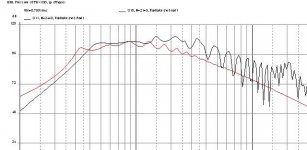
This included picture shows what can be done with a tapped horn
(equel input power)
Red=labhorn
Black=tapped horn 15"
I don`t think you can see the advantage of a tapped horn related to it`s distance from the mouth. It`s radiation patern and the extra forward directivity (depending on size) is not related specific to the tapped horn, it happens with all horns.
Check in Akabak the pressure (inspect, pressure) at the mouth of a tapped horn, do this the same time also with a vented box, but this time you put a transformer at the input of you vented box driver.
Fill in the parameters of the transformer in that way you get the same radiated dB level as the horn. Now check the excursion.
The adventage of a tapped horn can be seen.
This included picture shows what can be done with a tapped horn
(equel input power)
Red=labhorn
Black=tapped horn 15"
Attachments
Hi Ian: Thanks for posting your hornresp inputs.
Two things surprised me. First, some of your T/S numbers were different from B&C's published values. I'm betting that you checked their numbers and found some errors. Second, you used exponential rather than Conic expansion.
I duplicated your input screen in Hornresp and ran it. Then I "corrected" the inputs (B&C's numbers and conic flare), and ran it again. Yours was a little smoother, but I don't think I could have heard the difference.
I'm going to try a TH using a Kappalite 3015LF. I've got some wood cut, and hope to finish it this weekend.
Wish me luck,
Don Snyder
Attachments
Don Snyder said:Hi Ian: Thanks for posting your hornresp inputs.
Two things surprised me. First, some of your T/S numbers were different from B&C's published values. I'm betting that you checked their numbers and found some errors. Second, you used exponential rather than Conic expansion.
I duplicated your input screen in Hornresp and ran it. Then I "corrected" the inputs (B&C's numbers and conic flare), and ran it again. Yours was a little smoother, but I don't think I could have heard the difference.
I'm going to try a TH using a Kappalite 3015LF. I've got some wood cut, and hope to finish it this weekend.
Wish me luck,
Don Snyder
Hi Don
For the case I tried (given a fixed box size constraint) an exponential horn gives smoother response, probably because the mouth area is bigger than a conical horn. Even so the exponential cutoff is very low (<19Hz), so I'm going to try playing around with different expansion rates (slower then faster) to see if I can get even better response.
Best of luck with the sawing!
Cheers
Ian
- Home
- Loudspeakers
- Subwoofers
- Collaborative Tapped horn project