The room gain Dave is referring to can be quite serious. If you really want a flat frequency response you'll certainly end up having to cut some peaks with your current design. There's basically zero chance that it will be flat in your room.
That's why I suggested running some tests before building with an existing sub (borrow one if necessary), you don't need a precise measurement microphone or expensive software to get a rough idea of how your room will impact the frequency response. It could be substantial, like 12dB peaks. As mentioned a sealed box will be easier to EQ than the vented box, but I still prefer the vented. I would try and exploit the room gain to cut the cabinet size down even further and increase max SPL (less excursion for a higher tuning and smaller cabinet)
That's why I suggested running some tests before building with an existing sub (borrow one if necessary), you don't need a precise measurement microphone or expensive software to get a rough idea of how your room will impact the frequency response. It could be substantial, like 12dB peaks. As mentioned a sealed box will be easier to EQ than the vented box, but I still prefer the vented. I would try and exploit the room gain to cut the cabinet size down even further and increase max SPL (less excursion for a higher tuning and smaller cabinet)
Last edited:
out of interest i modelled a box version with standard construction techniques and 18mm mdf.
considering the box form is more space efficient ( for stacking maybe)
its impressive how much bigger it looks that the other two, with the cylinder appearing the smallest. if you overlay them you can see the box is smaller along its 90 degree axes than the cylinder, but the corners fill visual space much more.
Prefer the radius squared one.
This design brings back alot of memories! I started about 13 years ago making multi-layered horns out of 3/4" MDF, never going back to using that material again! I highly recommend using Baltic Birch (13-ply).
What kind of CNC machine do you have & what tooling / feed rates / software are you using?
ive not looked into the cnc aspect deeply yet. i have a friend in london who runs a cnc shop and owes me a favour, so i am hoping he will cut the stuff out for me.
ill be providing autocad dwg's of the shapes laid out, and whoever does the job will have to work out the cut offsets and correct tooling/feed rates etc.
i will also ask around locally, as being in southern Italy the shipping of the cut parts might be quite expensive!
if i have to actually pay for the cnc work (i.e. do it locally) ive no idea of the costs involved yet. hopefully not too prohibitive.
My first ever multi-layered sub I built back in 2001, external source for CNC work & using 1/4-20 threaded rods. I prefer using dowel rods & Harbor Freight clamps.
Attachments
i was referring to your suggestions of a 17 litre sealed enclosure and a vented box tuned to 20 hz.?
Right, forgot about the sealed box, i thot you were talking about the alignment w 2 different vents. IITC, F10 sealed was near 30 and the vented box just under 20 Hz.
Is there any logic to the idea of seeking the flattest response possible to allow more flexibility in eq?
As little EQ as possible is desired, and i don’t know that it would counter the large group delay.
Its much easier on the driver to subtract power at lower frequencies that try to bump it up.
True
also the extra extension provided by your proposals is all under 20 hz, where i would need a highpass anyway.
Why? You only need a filter below the tuning of the box to avoid driver unloading (not an issue with sealed)
ive already got big bookshelves, a giant sofa in the middle of the room, and pictures on most free wall surfaces. only zones available for any kind of treatment would be the curved cieling or the tiled floor. got some rugs down but carpeting would be a tragedy ( patterned vintage italian tiles)
I have hardwood floors, no rugs, so you are ahead in that respect.
ive spent weeks going through dozens of drivers to find one that can provide a flat response as low as possible...
Based on the T/S this driver does go very low.
dave
ok i am trying to produce a tweaked design closer to the ones suggested by Planet.
frustratingly reducing the box volume and increasing the port length leads to a larger overall enclosure. im trying to find a balance between all the measurements which gives the right results in a small footprint.
at the moment im quite close, but the port airspeed is nudging 26m/s
i understand that the slot has higher resistance which will affect this, and other parameters. maybe this will allow me to use a slightly shorter port...?
i read somebody suggesting that the port length calculator here:
Port Length Calculator
can properly model a slot port.
i input the information and it told me i should be using a 40cm port length!
bearing in winisd it tells me the port should be 1.2 metres long. this is quite wierd.
i thought maybe the difference really is that large, but if i toggle the "slot port" button on that page on and off, it only changes the suggested length slightly.
maybe this will allow me to use a slightly shorter port...?
A shorter vent also needs to have a smaller cross-section, but yes.
dave
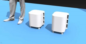
ok so ignoring that wierd website, and following the winisd guidance, here is the latest iteration.. its 17.4 litres internal, with 1.5x9cm slot ports, 1.2m long.
box is tuned to 23.5 hz.
The shorter one on the left is the new one.. its mainly shorter because ive switched to a realistic 18mm material thickness rather than the 20mm previously.
ive also increased the inner wall thickness to `15mm, and added some corner bracing.
the rounded rectangle design was chosen because a) i like it and b) it allows for longer grain lengths in the plywood, hence more rigidity (i think?)
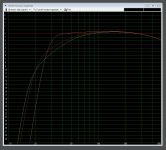
ive also attached the response curve, orange is my original, green was the suggestion by Planet, and the red is my new one which tries to keep cabinet size and port velocity down whilst approaching Planet's advised response curve.
one question.. how much space should i be leaving under the downfiring driver? its got an xmax of 11mm iirc..
box is tuned to 23.5 hz.
The shorter one on the left is the new one.. its mainly shorter because ive switched to a realistic 18mm material thickness rather than the 20mm previously.
ive also increased the inner wall thickness to `15mm, and added some corner bracing.
the rounded rectangle design was chosen because a) i like it and b) it allows for longer grain lengths in the plywood, hence more rigidity (i think?)
ive also attached the response curve, orange is my original, green was the suggestion by Planet, and the red is my new one which tries to keep cabinet size and port velocity down whilst approaching Planet's advised response curve.
one question.. how much space should i be leaving under the downfiring driver? its got an xmax of 11mm iirc..
Attachments

Clearance between down-firing sub and floor - AVS Forum | Home Theater Discussions And Reviews
Since yours is an 8" you could probably get away with 1.75" of clearance, but that's not exactly hard and fast.
The ones you've modelled as it is look about right.
You could consider empirical testing easily enough to be sure before finalising feet, but in any case when you do attach them it should be in a way that could be removed or adjusted later, in case tastes or circumstances change. Feet on a sub are often the first thing to wear down through extended use, even domestically (not to mention possible risk of a change in carpet situation)
You don't want the air to have to compress after leaving the face of the woofer, so you don't want the area of the space between the lowest point of the woofer (usually the mid-point of the surround) at the woofer's maximum excursion and the floor/board/top of carpet to be less than the piston area of the woofer.
Lets take a 12" woofer with a 10" distance from the top of the surround roll on one side to the top of the surround roll on the other side. We'll call that the effective piston diameter, so the piston area is 5 squared times pi = 78.5 sq.in..
The circumference of the surround at its peak is 10" x pi = 31.4" You need 78.5 square inches, so 78.5 divided by 31.4 = 2.5". But many woofers these days "excurse" quite a bit -- if you know the maximum one way excursion add that, or use 1/2 inch as an estimate -- add that to the 2.5" so that minimum clearance will be maintained even at peake excursion. In this case we'd want 3" minimum clearance between the woofer surround and the surface beneath.
Since yours is an 8" you could probably get away with 1.75" of clearance, but that's not exactly hard and fast.
The ones you've modelled as it is look about right.
You could consider empirical testing easily enough to be sure before finalising feet, but in any case when you do attach them it should be in a way that could be removed or adjusted later, in case tastes or circumstances change. Feet on a sub are often the first thing to wear down through extended use, even domestically (not to mention possible risk of a change in carpet situation)
… and the red is my new one which tries to keep cabinet size and port velocity down...
Looks even better than my 1st cut.
how much space should i be leaving under the downfiring driver?
Make it variable. You can tune the loading of the woofer by the proximity of the floor.
dave
So do you guys think i am good to go? Does the design look good? Vent shape and structural aspects seem reasonable? Im a touch concerned about the 1cm wide vent walls.. Its 15mm on the internal wall, so i can drill alignment holes in that part, but i dont think i should drill any alignment holes in the outer wall, its too thin.
However, if there is any warping of the slices after cutting, with no alignment pins in outer walls it might get a bit inaccurate? Misaligned outer faces would be horrible.
Having said that, it will be made from 18mm baltic birch ply, so maybe itll remain rigid enough between cutting and gluing to be ok.
I was checking the guide for an online cnc service. You provide a vector image (with all cut offsets included) and they send back the finished job.
However they state that the cutting bit is 8mm dia, so the smallest hole possible is 8mm, and the thinnest elements they accept in a design are 12.5mm
Its not a big deal to redesign with 12.5mm walls, but 8mm guide holes seem excessive.
Is this a standard bit size for cnc or will other people use thinner bits? Id also prefer somebody else to work out all the cut offsets etc. Unless it really is as simple as just doing a 4mm offset outside every line.
Yeah im having second thoughts about the thin ports.. The individual ports have an aspect ratio of 6:1, but since there are three, i think this means the aspect is actually 18:1? Or even worse? Not sure how to calculate it. The ports are also very long, and have lots of bends. Bit if a waste if it ends up behaving as a leaky sealed enclosure. Ive seen contradictory opinions on high aspect slots, some say it works fine, others that 1:4 is a rule-of-thumb limit. My port velocity at 250w is about 26m/s but it seems that is not the only thing i should consider.
Yes definitely be careful about the length of the port. The correct length is never the length WinISD says.
I saw a page of one bloke who ran tests that showed the actual vent length tended to be around 81% of the the simulation. It's certainly not going to be spot on though and it could be way off.
Long port with bends is no problem.
Port velocity of 26 m/s isn't an issue imo. 18:1 ratio slot port is a Bad Idea. Are you certain a properly divided slot counts as one slot? Definitely seek confirmation of this, but if it does turn out to be the case the simple fix while retaining the aesthetic would be to eliminate the centre port - you could maybe fit a badge into the recess where the middle port would have been if you were feeling vain...or a power button and an LED and make it active! That'd be sweet.
Last edited:
18:1 ratio slot port is a Bad Idea
I disagree. This is “common knowledge” that had proven not to stand. All of our miniOnkens (tens if not a hundred examples) have taken advantage of high ratio vents to get better bass — not necessariy lower but very nuanced.
That said, for big vents we are usually 12-15mm wide, our standmounts 7-9mm.
dave
Perhaps you can get away with it for certain hifi applications, but surely that doesn't mean it's not something to avoid as a rule of thumb until you know what you need. 'better bass' is really subjective, per the listener and per the design.
My understanding is pro audio based, and you certainly wouldn't make a high excursion 18" PA sub that's going to play concert levels, with a 36 x 2cm port.
The MiniOnken is 6" right? So 1300cc of vd at 10mm xmax. That 8" woofer with 11mm xmax is probably 2,400cc of vd. A high excursion 18 could move 18,000cc or more.
Does the amount of air moved through a port make any difference to acceptable ratios? I feel like it probably does but I can't back it up with science. I just imagine 18,000cc of vd trying to squeeze through such a thin slot and it doesn't feel like a good idea.
- Status
- This old topic is closed. If you want to reopen this topic, contact a moderator using the "Report Post" button.
- Home
- Loudspeakers
- Subwoofers
- the "swissroll" compact 8" subwoofer