Measurements
Sub1:
Fs: 26Hz
Qts: 0.978
Vas: 200L
Sub2:
Fs:28.2Hz
Qts: 1.137
Vas: 150L
Both subs have much lower distortion than I expected, especially Sub1.
I know said I'd go along with two chambers, but both have a very similar response at about 65L, so I'm going to mount them both into one 68L. 220W per driver will give me the SPL at 15Hz I'm wanting.
I've been reading lots. I see Vas doubles when you put 2 drivers into the same box. So I'm making the box 65 litres and mounting the woofers in an isobaric configuration. I'll start off with 140W and upgrade the amp if necessary. I don't have time now. I also have a stereo 52W, which may possibly do 90W in each, and i might use this. I'll measure first.
With two entirely different drivers they shouldn't be in the same chamber (as I said before) much less loaded isobaric.
Iso allows you to build a smaller box but it comes at the cost of 2x more power for the same max potential output as a single driver.
These are 10 inch drivers that you now want to put in an iso loaded sealed box and you expect to get usable 15 hz performance when eq'ed, correct? It's not going to happen, not even close, but it will be a good learning experience for you.
Hi JAG and All,
Here is an interesting application for two dissimilar drivers in a common enclosure:
http://community.fortunecity.ws/rivendell/xentar/1179/theory/dddllqd/dddllqd.html
So, it can be done; and I have mounted two different drivers together isobarically just playing around, and that can work too. Sorry, no nice write-up for that one.")
Regards,
Here is an interesting application for two dissimilar drivers in a common enclosure:
http://community.fortunecity.ws/rivendell/xentar/1179/theory/dddllqd/dddllqd.html
So, it can be done; and I have mounted two different drivers together isobarically just playing around, and that can work too. Sorry, no nice write-up for that one.
Regards,
so I'm going to mount them both into one 68L.
220W per driver will give me the SPL at 15Hz I'm wanting.
Hi,
Have you modelled volume displacement required for your SPL @ 15Hz ?
There is no chance two 10" in isobaric sealed will work well down to 15Hz.
(Or remotely handle that much power at 15Hz either.)
At the excursion limits 15Hz will be pretty much inaudible.
Seigfried Linkwitz as the originator of the Linkwitz transform suggests
first compensating the peaking Q to flat and then setting a new target
roll-off of critically damped, Q=0.5, -6dB, at say Fs is 20Hz to 30Hz.
Room gain will help, but the higher Fs is set, generally the louder
the sub will go, but not as deep. EQ deep limits maximum volume.
rgds, sreten.
Hi JAG and All,
Here is an interesting application for two dissimilar drivers in a common enclosure:
http://community.fortunecity.ws/rivendell/xentar/1179/theory/dddllqd/dddllqd.html
So, it can be done; and I have mounted two different drivers together isobarically just playing around, and that can work too. Sorry, no nice write-up for that one.
Regards,
Yes, of course you can do it and there might even be valid reasons to put two dissimilar drivers in the same enclosure but when the OP's stated goal is a strong 15 hz, there are no reasons at all to put two dissimilar drivers in the same enclosure or attempt to iso load them.
Also, while I'm sure iso loading dissimilar drivers can work, I doubt it could work optimally. One is naturally going to be stronger than the other, they will both have at least slightly differing cone motion, and to some extent the stronger one will be dragging the weaker one along. This would also apply to a much lesser extent when not iso loaded but placed in the same chamber. Sure, they will kind of "average out" but that's not optimal performance.
Last edited:
Hi JAG,
"...the OP's stated goal is a strong 15 hz..."
Considering all the trouble we got into trying to help Bach On to get to 16Hz while trying to work around driver and space limitations, I'm not going into that subject. Maybe if the OP would give consideration to a strong 35Hz instead; and that is not as easy as people seem to think.
Regards,
"...the OP's stated goal is a strong 15 hz..."
Considering all the trouble we got into trying to help Bach On to get to 16Hz while trying to work around driver and space limitations, I'm not going into that subject. Maybe if the OP would give consideration to a strong 35Hz instead
; and that is not as easy as people seem to think.Regards,
Wow, thanks - this is good stuff. I am indeed learning. And I have long forgotten about the 15Hz. But, I did mention I will be happy with 20Hz, which I also have found will not be easy. In #61, I made some uneducated assumptions, which I dismissed in the next post.
I wanted to try my best to get as close to the 20Hz as possible, but I see I have neither the space nor the money required. I have been pleasantly surprised with the Fs of the two drivers. It is lower than I had hoped (and so is distortion). Isobaric might not work out, but I'm going to give it a go. With one of those drivers mounted in the 65L enclosure, I should already get a good response to 30Hz, and that's already better than what I have.
I would love to calm the peak in the response at Fb (42 Hz), but I don't think I can achieve this mechanically. And anyway, the peak is where I want the response to be rolling off already, so it's out of the amplified range.
I bought some wood for cupboards yesterday, and I've cut the excess for a 65L woofer box. I'll be building it soon. If it doesn't work out, I haven't spent any money yet.
And thanks again. The reason for my OP and everything else is to learn. If I get something near what I ideally want, that's a benefit.
I'm not going to do much more than the basic theory in this design. I'll learn and do more for a later project if necessary.
Theoretically, with the isobaric configuration (and provided it works similar to what I believe it will), The response should be at -10dB at 20Hz. My amplifier is 140W. This is about 10dB more than 15W. 15W should give me 105dB on a flat response. So 140W should give me 105dB at about 20Hz. If I plan to make 20Hz my -3dB frequency, I should be able to achieve 108dB SPL for the overall bandwidth. That should be enough to complement my system perfectly. Currently I don't think I can get more than 103dB or so (and I rarely, if ever, use that sort of SPL).
Theoretically, with the isobaric configuration (and provided it works similar to what I believe it will), The response should be at -10dB at 20Hz. My amplifier is 140W. This is about 10dB more than 15W. 15W should give me 105dB on a flat response. So 140W should give me 105dB at about 20Hz. If I plan to make 20Hz my -3dB frequency, I should be able to achieve 108dB SPL for the overall bandwidth. That should be enough to complement my system perfectly. Currently I don't think I can get more than 103dB or so (and I rarely, if ever, use that sort of SPL).
I'm not going to do much more than the basic theory in this design. I'll learn and do more for a later project if necessary.
Theoretically, with the isobaric configuration (and provided it works similar to what I believe it will), The response should be at -10dB at 20Hz. My amplifier is 140W. This is about 10dB more than 15W. 15W should give me 105dB on a flat response. So 140W should give me 105dB at about 20Hz. If I plan to make 20Hz my -3dB frequency, I should be able to achieve 108dB SPL for the overall bandwidth. That should be enough to complement my system perfectly. Currently I don't think I can get more than 103dB or so (and I rarely, if ever, use that sort of SPL).
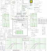
Hi Mrcloc,
Changing the prescription of the Sub(performance) again????See my simple calculations/plots of your first second suggested Sub:
I expect no comments again as for my first Posted Picture
b
Attachments
Hi bjorno. I didn't overlook the first analysis you posted, I certainly had a good look at it, thanks! The sub that I proposed was one that was sort of in my budget, and available. It was a point of discussion as a point of reference. I was told it wasn't good for my purpose, and the subs I'm going to use I have owned for long, so I don't need to buy anything else.
Thank you for the detailed analysis! I so appreciate it, and I'm going to study it at length! I like the results... At the moment I'm going to build my 68L box and mount the two isobaric to see what they can do. There is no harm in this, because I can simply add on the extra 68L chamber at a later stage. The filtering and amplifier will stay the same. And I believe I may convince my wife that the size is necessary.
The filter design you have there is great, thank you! It will be more suitable than my 2nd order design I proposed earlier.
You seem to enjoy creating thunderous bass... I'll update the thread on my progress.
Oh, and I'll post images of the drivers. The one's a Sakyno and the other's a Jensen (I don't know the model numbers, and I haven't found them online). I measured the parameters myself. I estimate Xmax to be > 8mm for both due to experience using these.
The sub that I proposed was one that was sort of in my budget, and available. It was a point of discussion as a point of reference. I was told it wasn't good for my purpose, and the subs I'm going to use I have owned for long, so I don't need to buy anything else.Thank you for the detailed analysis! I so appreciate it, and I'm going to study it at length! I like the results...
At the moment I'm going to build my 68L box and mount the two isobaric to see what they can do. There is no harm in this, because I can simply add on the extra 68L chamber at a later stage. The filtering and amplifier will stay the same. And I believe I may convince my wife that the size is necessary. The filter design you have there is great, thank you! It will be more suitable than my 2nd order design I proposed earlier.
You seem to enjoy creating thunderous bass... I'll update the thread on my progress.
Oh, and I'll post images of the drivers. The one's a Sakyno and the other's a Jensen (I don't know the model numbers, and I haven't found them online). I measured the parameters myself. I estimate Xmax to be > 8mm for both due to experience using these.
Great. I have a more suitable amp.
I built an amplifier for my brother to replace one I built long ago for him. The amplifier has given me issues, which I thought I had solved. I used the amp for long to test it, and when I took it to him, it reacted badly with his speakers. The old amp is incredible!
Anyway, this amplifier should easily and safely drive the two 4 ohm loads, and should do 90W into each, which gives me more headroom. It will also handle load variations perfectly fine. And it's a good place to put the amp because it appears to react well with inductive loads.
bjorno, I've read your entire analysis. What you've done there is pretty much exactly what I've had in mind. I'm doing it slightly differently. I don't need to calm the peak at Fb (Fo). In 65L (min), the peak is outside my bandwidth. I will be designing my filter a bit differently. But what I'm doing is pretty close to what you have shown, and you've really helped me, so thank you!
I've considered everything, and this will be my input filter:
It peaks at about 20Hz with a 1st order HPF there and a 2nd order LPF going further. It should give me a good compromise considering the response and the available power.
An externally hosted image should be here but it was not working when we last tested it.
It peaks at about 20Hz with a 1st order HPF there and a 2nd order LPF going further. It should give me a good compromise considering the response and the available power.
An externally hosted image should be here but it was not working when we last tested it.
I just want to add that I'm changing the filter ever so slightly - 4.7uF for C4, because I have it, and I can't easily make 6.6uF from the components I have. 4.7uF widens the band slightly and move the peak about 2Hz higher.
I also added a mixer amp on Vin, consisting of a summing amplifier with 22uF and 1kOhm input for each channel, and 1kOhm feedback, and the output goes through a 10k pot to this filter. I also changed R6 for a 27kOhm for a little extra gain.
I'm using a gainclone LM3886 for 80-90W into 4 ohms (+-31V supply). I have two gainclones, and I can run both off the same power supply if I add a second driver.
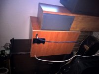
I built the box over the last while, and I've put together the LM3886-based amplifier. Driving 4 ohms isn't easy for the LM with the heatsink I have, so I'll load my second woofer in series to get 8 ohms. The heatsink will definitely cope with that!
Anyway, it's working VERY well! I get very strong response down to 23Hz, and it seems to roll off from there. The peak in the response (by ear) is between 22Hz and 35Hz. And it's quite efficient too, making the windows shake at only a few mW average (it was 2am, and I couldn't really give it much more).
Anyway, it's working VERY well! I get very strong response down to 23Hz, and it seems to roll off from there. The peak in the response (by ear) is between 22Hz and 35Hz. And it's quite efficient too, making the windows shake at only a few mW average (it was 2am, and I couldn't really give it much more).
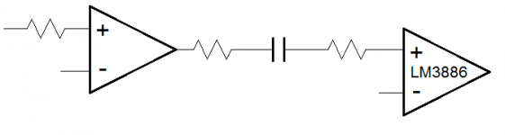
I meant to attach this. This configuration does not work! The first op amp is the output amplifier of the input filter. Do not couple like this. When I built the circuit I saw this was going to happen and had my doubts. Just connect the filter output directly to the 1k input resistor of the LM3886. Remember that the DC gain of the LM3886 in the typical application circuit is 1.
I thought I'll try the configuration attached to see how it worked (with all my doubts), and it's not good. The DC offset on the output climbs quickly. It starts off at -100mV, and linearly decreases until you power down. I'm not sure where it will stop, but when it gets big, the heatsink gets very hot very quickly. In addition, there is an ugly crackling noise with hissing on the output. I suspect SPiKE or whatever it's called kicking in due to the DC protection. When volume is high enough, the protection stops. Anyway, when there is a DC output and a hot chip, the turn off is alarming! Ugly noises.
I thought I'll try the configuration attached to see how it worked (with all my doubts), and it's not good. The DC offset on the output climbs quickly. It starts off at -100mV, and linearly decreases until you power down. I'm not sure where it will stop, but when it gets big, the heatsink gets very hot very quickly. In addition, there is an ugly crackling noise with hissing on the output. I suspect SPiKE or whatever it's called kicking in due to the DC protection. When volume is high enough, the protection stops. Anyway, when there is a DC output and a hot chip, the turn off is alarming! Ugly noises.
Attachments
- Status
- This old topic is closed. If you want to reopen this topic, contact a moderator using the "Report Post" button.
- Home
- Loudspeakers
- Subwoofers
- Subwoofer build - where do I start?