AkAbak uses the Webster plane wavefront model to calculate horn throat acoustical impedance, where the horn mouth impedance is assumed to be that of a plane vibrating piston. The throat acoustical impedance determines how much acoustical power is transmitted / propagated down the horn, and consequently radiated by the horn. A more accurate prediction can be obtained using an isophase wavefront model.
This is to calculate the directivity of the horn - a different issue to calculating the radiated acoustical power.
Just to clarify:
The gain and extension of bass are due to the improved acoustical loading and reduced solid radiation angle at the normal horn mouth, as a result of the 0.5 x pi (eighth-space) conditions.
The gain and extension are due to the improved acoustical loading and reduced solid radiation angle at the horn mouth, as a result of the 2 x pi (half-space) conditions.
I'm clearly not an expert when it comes to knowing exactly what the simulators are assuming internally in all situations, especially the math. But from this, it sounds like in Hornresp's case you would agree that the simulator doesn't need to concern itself with the bubble AT ALL, only the resulting throat acoustical resistance from the enclosure and the boundaries near the enclosure (which are assumed to be infinite size). The boundaries provide a simple reflection, 6db per boundary, which is exactly the same effect as diffraction when the boundary is larger than the lowest wavelength. The sim is just correct, you don't need to mess around with artificially adding horn length to account for the bubble (ever) and you don't need a reduced mouth size to properly form the bubble.
If there are any mistakes in the preceding paragraph please let me know. If not, this is exactly what I've been saying. About a hundred times.
Moving on to Akabak, this software is a bit more flexible in that it can calculate diffraction from a finite boundary (which is not as simple as a simple reflection at 6db per boundary) but it can't simulate the bubble because of Webster. So the bubble would have to be added manually. But the bubble will only add a few inches and maybe 1 hz extension with the horns sizes we are dealing with.
Again if there are any mistakes there, let me know. Also, is it possible to manually add the bubble? What would that look like? Each segment gets a small added length, or one extra segment is added at the end?
Finally, I'm assuming you don't want to give your opinion on how this type of boundary extension should be simulated, otherwise you would have by now. But I'm going to go ahead and ask your opinion anyway. Do you think an sim including diffraction is going to do the job (or get at least most of the way there)?
Just a guy or any other do we have a notion as to which 18's DSL is using in their BC218? Or 15's in their BC415?
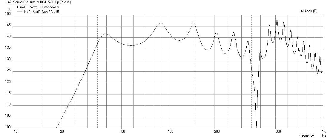
My sim of the guess of what a BC415 may look like assumes a B&C 15SW115 driver. I was able to hit 142dB xmax limited in 4-parallel drivers at 1600 watts a piece. The response max SPL and peaks at 38Hz, 92Hz, and 190Hz kind of look like the response for the BC415 shown by DSL. Given the max power rating specified by DSL as 1700watts ea, I think I might be very close. My peak power also ended up at 87Hz - the same value as the peak power spec for the BC415. I think it is probably 85% certain that the B&C 15SW115 is the correct driver.
Here is my sim at xmax again:
Does look pretty close. Although I am sure the real feat would be in folding that monster. I wouldnt mind doing a dual 18" BC that has low extension but four 15's is pushing the budget to much to try.
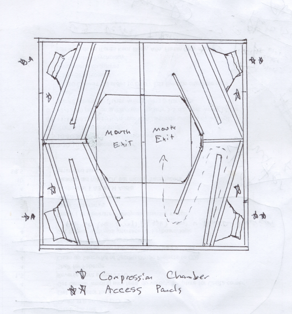
The fold scheme is quite simple actually - see guess made by Weltersys - provides the path length needed.
The cost of the drivers is not the issue ($2000), it's where do you keep a 60x60x26 in box that weighs 500lbs?
I have so many carcasses in my shed that I could fit one in there if I got rid of the 3 other cabinets that need to go. 3" casters and no problems. For me its more of a money thing. Not saying that I could use the 18 Sound 18LW2500 but they are about 700 for me for a pair. SO easier for me to deal with budget wise verse four 15's albeit more SPL.
PLUS for me it is difficult and expensive to find 60x60 sheets of ply. Only have 48 x 96 for myself. 120 sheet for that is enough for me. BB in 60 x 60 is a LOT more expensive. Although I cant remember the sizes of the BC218 so maybe that one is to big also.
PLUS for me it is difficult and expensive to find 60x60 sheets of ply. Only have 48 x 96 for myself. 120 sheet for that is enough for me. BB in 60 x 60 is a LOT more expensive. Although I cant remember the sizes of the BC218 so maybe that one is to big also.
It doesn't have to be made from one sheet. The sub can be split into two halves and made modular. You can bring them together to get the full Monty or use half and half for a stereo pair ")
Use some hardware to bolt them together side by side. May make transport a bit easier too.
Use some hardware to bolt them together side by side. May make transport a bit easier too.
The fold scheme is quite simple actually - see guess made by Weltersys - provides the path length needed.
The cost of the drivers is not the issue ($2000), it's where do you keep a 60x60x26 in box that weighs 500lbs?
Ok, I'll bite - what makes this better than four folded horns, one for each of the driver indicated? I'm going to guess that four separate horns are a lot easier to move around than that behemoth.
If the radiator at the mouth of a "Horn" element is indeed many smaller radiators with overall curvature, is the impedance at the mouth still that of a plane vibrating singular piston?
Not if the multiple radiators are used to calculate mouth impedance, but in the case of the AkAbak "Horn" element, they are used to calculate directivity only. The mouth acoustical impedance is still calculated assuming a plane vibrating piston, as previously mentioned.
Regarding accuracy of isophase model - I am not sure how much more accurate the isophase assumption from the throat is in most practical horns where folds and bends are introduced which are then modeled in AkAbak using more segments of waveguides with expanding then contracting cross sectional area.
There is very little difference between the plane wavefront model and the isophase wavefront model up to the point at which the horn mouth size exceeds Cir = 1, where Cir is the free space normalised horn mouth circumference in flare cutoff frequency wavelengths, assuming an axisymmetric horn. The Webster model is entirely adequate for most bass horn designs, straight or folded, because the mouth size is usually less than Cir = 1.
For straight horns I will agree that isophase can be more accurate for systems where the wavefront has a lot of curvature.
That is the point I wished to make - that the plane wavefront model becomes inaccurate when applied to Le Cléac'h, tractrix, radius and spherical wave horns.
However, as most folks will agree that HR is superb for ease of use and user friendly features and for its ability to predict responses in a real time slider based wizard mode. I thank you for all you have done to give the DIY community such a superb tool. Frankly, most people here would not have been able to design all the TH's that are proliferating the threads without your software as they find AkAbak too daunting to overcome the learning curve.
Thanks for the kind words. AkAbak is excellent for modelling more complex designs, which is why there is an AkAbak script export feature in Hornresp. The two programs complement each other very nicely indeed
.But from this, it sounds like in Hornresp's case you would agree that the simulator doesn't need to concern itself with the bubble AT ALL, only the resulting throat acoustical resistance from the enclosure and the boundaries near the enclosure (which are assumed to be infinite size).
The Hornresp isophase model is very concerned with the "bubble", if by bubble you mean the curved wavefront at the mouth of the horn. This is because the assumption made on the shape of the wavefront at the mouth affects the mouth acoustical impedance, which is ultimately "transformed" down the horn to become the throat acoustical impedance.
The boundaries provide a simple reflection, 6db per boundary, which is exactly the same effect as diffraction when the boundary is larger than the lowest wavelength.
In Hornresp, the infinite "boundaries" define the solid angle into which the horn radiates, which (along with the shape of the mouth wavefront) determines the mouth impedance. Reflections and diffraction do not come into the considerations.
Moving on to Akabak, this software is a bit more flexible in that it can calculate diffraction from a finite boundary (which is not as simple as a simple reflection at 6db per boundary) but it can't simulate the bubble because of Webster. So the bubble would have to be added manually. But the bubble will only add a few inches and maybe 1 hz extension with the horns sizes we are dealing with.
Again if there are any mistakes there, let me know
The above comments seem okay.
Also, is it possible to manually add the bubble?
No, not for the purposes of more accurately calculating the mouth acoustical impedance.
What would that look like?
A curved wavefront surface at the mouth of the horn, approximating a spherical cap (imagine a balloon expanding slightly out of the horn).
Each segment gets a small added length, or one extra segment is added at the end?
The isophase wavefront model requires each segment to have a small added length.
Do you think an sim including diffraction is going to do the job (or get at least most of the way there)?
If diffraction can be accurately taken into account, then presumably the overall prediction will be better. Hornresp does not do this, and I am not familiar with the diffraction model used in AkAbak.
The Hornresp isophase model is very concerned with the "bubble", if by bubble you mean the curved wavefront at the mouth of the horn. This is because the assumption made on the shape of the wavefront at the mouth affects the mouth acoustical impedance, which is ultimately "transformed" down the horn to become the throat acoustical impedance.
Ok, so I worded my questions badly. I think a lot of that is due simply to the fact that I don't know the math behind the sims. Let's try again.
Does Hornresp do anything other than the isophase model to calculate the bubble? We already knew Hornresp accounts for the bubble and the isophase model is responsible for that. But does Hornresp have to do anything outside the isophase model to account for the bubble? Like for example change the horn length by adding length to the horn to account for the bubble? From my understanding the isophase model itself accounts for the bubble so there's nothing else Hornresp needs to do to account for it. That's what I was asking. Not very coherently, apparently.
In Hornresp, the infinite "boundaries" define the solid angle into which the horn radiates, which (along with the shape of the mouth wavefront) determines the mouth impedance. Reflections and diffraction do not come into the considerations.
I'm not sure how diffraction or solid angle radiation are expressed mathematically but I'm pretty sure Akabak's diffraction model is going to do the job. I haven't tried yet, but if you use the diffraction feature in Akabak and set the size it infinite I'm pretty sure it would act the same as a solid angle into which the horn radiates, same as what Hornresp does by increasing Ang. Setting the boundary smaller than infinite should work just fine for simulating a boundary extension.
No, not for the purposes of more accurately calculating the mouth acoustical impedance.
This sounds like it contradicts your following statement - "The isophase wavefront model requires each segment to have a small added length." The small added length won't correct the mouth acoustical impedance?
A curved wavefront surface at the mouth of the horn, approximating a spherical cap (imagine a balloon expanding slightly out of the horn).
I know what a bubble looks like. I was asking what the manual correction for the bubble would look like and you answered that - "The isophase wavefront model requires each segment to have a small added length." But you also mentioned it won't work for the purposes of more accurately calculating the mouth acoustical impedance.
If diffraction can be accurately taken into account, then presumably the overall prediction will be better. Hornresp does not do this, and I am not familiar with the diffraction model used in AkAbak.
I guess that last question is the only one that I worded properly.
The only thing I care about is how to simulate things properly. I hate to keep coming back to this because we don't know how accurate Weltersys' guess of the the internals is, but Xrk's sim (including diffraction) is VERY close and he didn't have to come up with any radical new way to account for this "boundary bubble".
Too many people think there's some kind of black bubble magic going on that either can't be simulated at all or only Danley can simulate. My position is that there is nothing special going on that we can't simulate easily, just like any other design with an extended boundary, like a tweeter on a baffle. Even with a sim that matches so closely, people want to believe something else entirely is happening.
Last edited:
Too many people think there's some kind of black bubble magic going on that either can't be simulated at all or only Danley can simulate. My position is that there is nothing special going on that we can't simulate easily, just like any other design with an extended boundary, like a tweeter on a baffle. Even with a sim that matches so closely, people want to believe something else entirely is happening.
I've got a black magic bubble...got a black magic bubble..
I've got a black magic bubble...got me so blind I can't see...
Guys, I'm really enjoying the technical discussion, thank you all.
jn
Mr. McBean's post (especially the fact that he thought I was asking what a bubble looks like) informs me of the extent to which I am probably being misunderstood. So just to make things REALLY clear:
What I am proposing as an accurate way to simulate this is:
1. Sim the internals, as normal.
2. Add diffraction to the sim to account for the boundary extension outside the horn mouth.
3. Since this is being done in Akabak and the bubble is not accounted for, either disregard the bubble completely like we do for all other Akabak sims up to this point or manually account for the bubble at the mouth exit (which will be a small bubble) - not at the boundary edges (which would be a large bubble).
Danley said the bubble extends forward somthing like 60 percent of mouth radius. So if the mouth was 20 inches wide and you wanted to manually account for the bubble you would add about 6 inches to the horn length (a couple inches per segment as per McBean's last post). This is regardless of the boundary size, step 2 (diffraction) takes care of accounting for the boundary size.
I have a feeling people would rather add 18 inches (60 percent of the radius of the 60 inch wide boundary) because that's how big Danley said the bubble is, but my point is that we don't have to worry about the bubble after it exits the mouth, the diffraction part of the sim accounts for that.
I really hope that is clear enough.
I also hope this illustrates how much this issue really matters (or more accurately doesn't matter unless accurate sims are a top goal like they are for me) - the difference between the forward length of a bubble 20 inches in diameter vs 60 inches in diameter is 12 inches. Maybe 1 hz extension in a sim. This is within the normal range of error in any sim anyway. And let's not forget that up to this point nobody ever concerned themselves with the bubble in Akabak sims and nobody really noticed much (if any) difference when compared to Hornresp sims of the same enclosure.
Mr. McBean's post (especially the fact that he thought I was asking what a bubble looks like) informs me of the extent to which I am probably being misunderstood. So just to make things REALLY clear:
What I am proposing as an accurate way to simulate this is:
1. Sim the internals, as normal.
2. Add diffraction to the sim to account for the boundary extension outside the horn mouth.
3. Since this is being done in Akabak and the bubble is not accounted for, either disregard the bubble completely like we do for all other Akabak sims up to this point or manually account for the bubble at the mouth exit (which will be a small bubble) - not at the boundary edges (which would be a large bubble).
Danley said the bubble extends forward somthing like 60 percent of mouth radius. So if the mouth was 20 inches wide and you wanted to manually account for the bubble you would add about 6 inches to the horn length (a couple inches per segment as per McBean's last post). This is regardless of the boundary size, step 2 (diffraction) takes care of accounting for the boundary size.
I have a feeling people would rather add 18 inches (60 percent of the radius of the 60 inch wide boundary) because that's how big Danley said the bubble is, but my point is that we don't have to worry about the bubble after it exits the mouth, the diffraction part of the sim accounts for that.
I really hope that is clear enough.
I also hope this illustrates how much this issue really matters (or more accurately doesn't matter unless accurate sims are a top goal like they are for me) - the difference between the forward length of a bubble 20 inches in diameter vs 60 inches in diameter is 12 inches. Maybe 1 hz extension in a sim. This is within the normal range of error in any sim anyway. And let's not forget that up to this point nobody ever concerned themselves with the bubble in Akabak sims and nobody really noticed much (if any) difference when compared to Hornresp sims of the same enclosure.
My Q is, what is the boundary compliance of the bubble? It's not a hard surface after all, but one that should be removing energy from the "formed" wavefront edges.
I wonder if there's any way to shape the exit edges to bolster the hardness of the whorl defining the bubbne edge and return energy being bled off.
jn
I use Smaart V6, I don't know what the differences between 5 and 6 are, but the current version supports multiple microphones, a very nice feature for tuning systems using multiple speakers for coverage of individual areas.Hey, quick question: I have an old Smaart 5.x license.....would you upgrade it or plow into the REW freeware?
For the usual measurement of a single speaker, any version of Smaart should be adequate. For in room tuning, I think pink noise is a better source than the swept sine REW (and many other expensive programs) uses.
That said, I will be diving in to REW shortly, as it includes a distortion analyzer, a feature not included in Smaart V6. Although one can look at the Smaart RTA screen of a single frequency sine wave to see HD, to do that with enough frequencies to paint a picture takes a long time, and still may miss data points, as some HD can be limited to a very narrow band width.
Art
Having moved around single large cabinets and four small cabinets equal to the size, on smooth terrain moving the single large cabinet requires less effort- one trip from the truck to stage is a lot easier than four.Ok, I'll bite - what makes this better than four folded horns, one for each of the driver indicated? I'm going to guess that four separate horns are a lot easier to move around than that behemoth.
A single cabinet uses less wood, so is lighter than four cabinets of the same enclosed volume.
At any rate, multiple driver BC (or any type of folded horn) designs can be made as single or multiple driver cabinets to fit various transportation and storage requirements. Presently, as a small time operator, the flexibility two or four cabinets provide is an advantage, though when I was working on a large scale (over 100 sub drivers) quad loaded cabinets were preferable.
Art
In Hornresp the infinite boundaries are also assumed to be surrounding the circular horn mouth, in actual use that would require digging a hole in the ground to mount the cabinet in, or soffit mounting the cabinet in walls or corners.In Hornresp, the infinite "boundaries" define the solid angle into which the horn radiates, which (along with the shape of the mouth wavefront) determines the mouth impedance. Reflections and diffraction do not come into the considerations.
In reality, the cabinet is usually mounted on a surface of the plane, the distance that the cabinet "sticks out" from the plane (and the area of the boundary plane the horn exit baffle creates) will cause frequency deviations and sensitivity different from the prediction.
For designs like the BC type horns, Akabak has the requisite features to model the rectangular shape and usual proximity to boundaries.
Xrk91's recent simulation shows good correlation to the BC415 measured results.
Other than some throat details I suspect are employed not shown in my simple sketch, I think building from it, using BC15SW115 drivers would result in a cabinet with response very similar to the DSL BC415.
Art
I also hope this illustrates how much this issue really matters (or more accurately doesn't matter unless accurate sims are a top goal like they are for me) - the difference between the forward length of a bubble 20 inches in diameter vs 60 inches in diameter is 12 inches. Maybe 1 hz extension in a sim. This is within the normal range of error in any sim anyway. And let's not forget that up to this point nobody ever concerned themselves with the bubble in Akabak sims and nobody really noticed much (if any) difference when compared to Hornresp sims of the same enclosure.
I had to add 16in to the length of the horn to get it to match Danley's measured response based on an 88in path length derived from Weltersys' guess of the internals. If the internal path somehow squeezed another 16in (could be possible), then I did not need to add the 16in. The 16in, btw, is equal to 60% of the mouth dia.
I have tried to sim the "bubble" as a very wide and short horn with a throat equal to the mouth aperture and the horn exit equal to the baffle size of 60x60 inches and a small path length of 1in, which is flat for all intents and purposes. It did not change the bass extension, but it does change the amplitude - so in effect, may be considered shifting the extension if you normalize with respect to the amplitude without the wide bubble horn fudging horn that I added. This fudging bubble horn, btw, is very sensitive to length. You get quite a bit of gain for a 4 inch long vs a 1 in long "bubble horn". Just food for thought.
I had to add 16in to the length of the horn to get it to match Danley's measured response based on an 88in path length derived from Weltersys' guess of the internals. If the internal path somehow squeezed another 16in (could be possible), then I did not need to add the 16in. The 16in, btw, is equal to 60% of the mouth dia.
You don't necessarily need length to get lower tuning. Like I said before there's a few tweaks you could make to get the sim to match better without adding length. Things that are entirely possible based on what we know about the cab (only a picture of the front of the box is all we really know, in other words mouth details). A different flare rate starting with a larger throat should tune a bit lower and not add any length. I'm not sure what throat size you used, but Danley doesn't usually go too much higher than 2:1 compression ratio (which is unusually low for designs around here) so it's entirely possible your simulated throat is too small. Also, as Weltersys just mentioned, it's possible and probably even likely that the beginning of the line is flared out like the TH-SPUD, so that S1 is much larger than S2.
Changing the flare rate and adding 6 inches for the mouth bubble (not 18 for the boundary bubble) should get you just about where you need to be.
The rear chamber size might need a bit of tweaking too, maybe not. I didn't want to get into the "match the measurement better by tweaking the inputs" game because it may or may not accurately reflect the internals of the actual box, but at the same time since we don't know it's worth looking into what might be in there.
Last edited:
My Q is, what is the boundary compliance of the bubble? It's not a hard surface after all, but one that should be removing energy from the "formed" wavefront edges.
I wonder if there's any way to shape the exit edges to bolster the hardness of the whorl defining the bubbne edge and return energy being bled off.
jn
I'm not sure what you mean. The bubble is just the wavefront shape. Not sure what "whorl" you are talking about, or the removing energy from the edges but it sounds like the vortex theory a few pages back.
I don't think the airflow out the mouth is creating a virtual flare out of thin air. If it did, it wouldn't work until moderately high power output and would be continuously variable in size and shape with variable power input.
- Status
- This old topic is closed. If you want to reopen this topic, contact a moderator using the "Report Post" button.
- Home
- Loudspeakers
- Subwoofers
- Danley BC-subs reverse engineered