Hi Djim,
Would this be enough of a cone correction:
Regards,
I just wanted to say that I really appreciate the additional discussion of these 12" designs in this thread. Without some of the advice here, I would have focused on the wrong things. I would have under emphasized the importance of bracing and I would have been overly concerned that the horn taper had to be just so. Now with the additional information of the last few pages, I feel that I can put my own simulation attempts on firmer footing.
So, thanks,
gs
Hi Oliver,Would this be enough of a cone correction:
If you go that far you will increase the pressure on the cone towards the centre (of course depending on the shape of the cone). Since the Tham12 seems to be designed for relative low BL drivers I would try something smaller;
Hi Djim,
The B&C 12PS100 has a listed BL of 22.5 Tm. Depending on the cone's shape I think you could be a little more aggressive, as long as the remaining cross-section does not fall below the S2 value from Hornresp, don't you think?
Regards,
The B&C 12PS100 has a listed BL of 22.5 Tm. Depending on the cone's shape I think you could be a little more aggressive, as long as the remaining cross-section does not fall below the S2 value from Hornresp, don't you think?
Regards,
Hi Oliver,The B&C 12PS100 has a listed BL of 22.5 Tm. Depending on the cone's shape I think you could be a little more aggressive, as long as the remaining cross-section does not fall below the S2 value from Hornresp, don't you think?
Agreed, for the B&C 12PS100 you could go for a higher stub. My quick analyse your stub ended with the same top of the stub (where it hits the driver baffle) but with a slightly smaller base, probably the result of a different cone-shape.
Don't you think the S1 area needs to be enlarged to keep the pressure on that side a little lower (compensation for the increased pressure)?
Also I agree with Brian's remark, the S4-S5 section could benefit from some compensation. Also, the end-widening in the last 5 to 10cm (mouth area) will not be seen by relative large wavelengths. It will only affect relative high frequencies. That's is why I believe the mouth area in Xoc1 model is too large in relation to low frequency behaviour.
Last edited:
Hi Djim,
Post #105: "...Don't you think the S1 area needs to be enlarged to keep the pressure on that side a little lower (compensation for the increased pressure)?"
There are about 2-1/2" between the edge of the woofer and the right angle bend of the horn, setting the woofer back into the horn (e.g.: 1.5"[4cm]) might be a good thing, but it will reduce L23.
As to the mouth size, I'd just go with whatever Hornresp says works. The mouth section should probably be simulated as Exp, or maybe this whole thing is so tweaked that it needs to be put into AkAbak.
Regards,
Hi Oliver,As to the mouth size, I'd just go with whatever Hornresp says works. The mouth section should probably be simulated as Exp, or maybe this whole thing is so tweaked that it needs to be put into AkAbak.
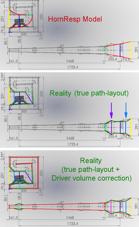
I agree, the reality is 'so tweakes' that taking the S1 points no longer actually represents the true path. By re-modeling after measurments of freq and phase responses, you can compensate for the minimum amount of S-points HornResp is currently offering. Indeed, the other way is going with Akabak...
Apologies for the sim at the wrong voltage. As mentioned by Chaps the 2.83V level is about 1.5db higher.It will only affect relative high frequencies. That's is why I believe the mouth area in Xoc1 model is too large in relation to low frequency behaviour.
I agree with DJim that the mouth area in my sim is could be too large as the expansion is over a relatively short area, but S4 is also considerably smaller due to the driver cone and chassis, so the final expansion is probably more linear over a larger area than suggested by the shape of the final flare utilising the reflector.
Has anyone got a typical cross sectional area figure for a 12" driver that might be deducted from S4 to get a better idea of what the final expansion is?
Gentle cone correction does seem to improve the bandwidth and fill in the dip at 180 hz. Its easy to see the effect by zeroing Ap1 and Lpt in the sim.
Any more than that and we are moving into Akabak territory.
EDIT DJim you beat me to it by a couple of minutes🙂
Regards
Xoc1
Last edited:
Hi Martin,Its easy to see the effect by zeroing Ap1 and Lpt in the sim.
I am not sure if the Atc/Vtc function within HornResp is the best method to emulate the cone-volume at S2. I think it is meant to simulate true 'chamber' function (an impedance transformer) since it simulates a true air column. I think that the cone volume is just added to the S2 horn section because of the very shallow cone-shape instead of a true column/chamber. Well, maybe it doesn't matter much...
(Btw thanks for your great drawings again)
Last edited:
@ Xoc1: I think 200 cm^2 does about cut it. I like to make L34 quite small in this case, leaving a single segment for the rest, standing on the verge of AkAbak.
Best regards Johan
Best regards Johan
Hi Xoc1,
Post #108: "...a typical cross sectional area figure for a 12" driver that might be deducted from S4..."
I scratched out something for the 12PS100, should work plus minus a few cm^2 (I'm just guessing at the cone shape.). (For the OP: S4 if you use a 4-section Hornresp model, S3 for a 3-section model.)
Regards,
Attachments
Djim or Tb46
Can some please post a drawing and measurement of the cone correction for the b&c 12PS100 driver.
Can some please post a drawing and measurement of the cone correction for the b&c 12PS100 driver.
Hi kornnylike,
I'm just doing this from the driver drawings and pictures. I don't have a driver at hand to measure the cone shape/position. I'll attach a suggestion if you or somebody else wants to take a first stab at it, or if someone wants to add his comments (always highly appreciated):
Regards,
I'm just doing this from the driver drawings and pictures. I don't have a driver at hand to measure the cone shape/position. I'll attach a suggestion if you or somebody else wants to take a first stab at it, or if someone wants to add his comments (always highly appreciated):
Regards,
Attachments
Tb46 I just order that driver I should get it next week. I can measure it if you want
I will start making saw dust this weekend for a new tapped horn using the b&c 12ps100
I will start making saw dust this weekend for a new tapped horn using the b&c 12ps100
Last edited:
Hi kornnylike,
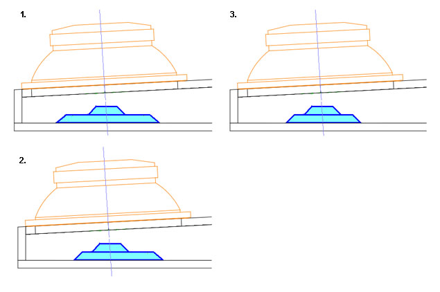
It took some time but I have gone for a similar approach that I've used for the Xoc1-TH18. The side cuts are 45 degrees. You will see that both parts have a small difference in centre. That is to compensate they are attached under an angle in relation to the driver baffle.
It took some time but I have gone for a similar approach that I've used for the Xoc1-TH18. The side cuts are 45 degrees. You will see that both parts have a small difference in centre. That is to compensate they are attached under an angle in relation to the driver baffle.
An externally hosted image should be here but it was not working when we last tested it.
Hi kornnylike,
It took some time but I have gone for a similar approach that I've used for the Xoc1-TH18. The side cuts are 45 degrees. You will see that both parts have a small difference in centre. That is to compensate they are attached under an angle in relation to the driver baffle.
An externally hosted image should be here but it was not working when we last tested it.
Nice
Forget that drawing, cause I have made a mistake. Since I have to do it all by hand it takes time.......grrrrrr
Last edited:
The error wasn't big I think, just a couple of mm. Pfffff
An externally hosted image should be here but it was not working when we last tested it.
Hi kornnylike,
Post #114: "...I can measure it..."
That would be great.
Regards,
Ok
- Home
- Loudspeakers
- Subwoofers
- MTH30 Questions : Complete Noob!