Thorn F1 -Tapped Horn Experiments
Thorn F1, Tapped Horn Experiments
This is a thread about my attempts to build and better understand Tapped Horn loudspeakers. I started out with a simple build and want to share my ideas and hopefully get some feedback on my thoughts.
Martinsson often emphasis the strength in collaboration and the open source atmosphere. What I have learned so far about DIY hifi is all thanks to that attitude and the people who share that belief. I hope to start a thread that can contribute to that DIY collaboration thought and mutual learning.
OK, loudspeakers for bass!
I want bass in my home and I want it to be clean, loud and accurate. I have looked at different options to reproduce bass mostly variations on Transmission Lines and Mass Loaded Transmission Lines but finally decided to go with Tapper Horn, for now.
My design goals are:
I am a great fan of Anders Martinsson and his THAM designs which have been a significant source of inspiration in this build. I have also got a lot of help and feedback on this design on HiFiForum.nu from many, espessially Circlomanen, petterpersson and Martinsson just to mention a few.
I am appealed of the robustness of PA elements and I really do like Eighteensounds products. When I did get the opportunity to buy a new pair to a heavy discount I couldn’t resist the temptation. The element of choice is 12LW800. I think it is very suitable for tapped horns with high BL, high fs, low Qts and fairly long excursion. Other elements that is suitable in this design without any adjustments are Beyma 12LX60, EighteenSound 12LW1400. Thanks to their longer X-max (9 mm) they will provide even higher max SPL.
Speaking of robustness; I think one can use the 12LW800 to support a car when changing tires without damaging it. The basket is built like a tank.
Internal with: 42 cm exclusive bracing.
The cabinet is just for trying out the concept. I have therefore used the cheapest particle board available and not gone for Baltic Birch Plywood or something similar at this stage.
Maybe I didn’t meet all my goals but quite a few I think. 🙂
/Forsman
My newly started blogg: DIY Open Source Hifi
Thorn F1, Tapped Horn Experiments
This is a thread about my attempts to build and better understand Tapped Horn loudspeakers. I started out with a simple build and want to share my ideas and hopefully get some feedback on my thoughts.
Martinsson often emphasis the strength in collaboration and the open source atmosphere. What I have learned so far about DIY hifi is all thanks to that attitude and the people who share that belief. I hope to start a thread that can contribute to that DIY collaboration thought and mutual learning.
OK, loudspeakers for bass!
I want bass in my home and I want it to be clean, loud and accurate. I have looked at different options to reproduce bass mostly variations on Transmission Lines and Mass Loaded Transmission Lines but finally decided to go with Tapper Horn, for now.
My design goals are:
- Bass with high quality and ability to play loud
- Extension downwards to be able to reproduce the lowest note of a normal electric bass guitar (about 41 Hz I think).
- Cabin depth of max 50 cm
- I do want as much “kick” as possible without sacrificing the bass around 40-50 Hz.
- Possibility to cross over as high as 150 Hz
- High efficiency with max SPL at X-max of at least 125 db at 1m in 1 pi
- Manageable size for domestic use.
I am a great fan of Anders Martinsson and his THAM designs which have been a significant source of inspiration in this build. I have also got a lot of help and feedback on this design on HiFiForum.nu from many, espessially Circlomanen, petterpersson and Martinsson just to mention a few.
I am appealed of the robustness of PA elements and I really do like Eighteensounds products. When I did get the opportunity to buy a new pair to a heavy discount I couldn’t resist the temptation. The element of choice is 12LW800. I think it is very suitable for tapped horns with high BL, high fs, low Qts and fairly long excursion. Other elements that is suitable in this design without any adjustments are Beyma 12LX60, EighteenSound 12LW1400. Thanks to their longer X-max (9 mm) they will provide even higher max SPL.
Speaking of robustness; I think one can use the 12LW800 to support a car when changing tires without damaging it. The basket is built like a tank.
An externally hosted image should be here but it was not working when we last tested it.
Internal with: 42 cm exclusive bracing.
An externally hosted image should be here but it was not working when we last tested it.
An externally hosted image should be here but it was not working when we last tested it.
An externally hosted image should be here but it was not working when we last tested it.
An externally hosted image should be here but it was not working when we last tested it.
An externally hosted image should be here but it was not working when we last tested it.
The cabinet is just for trying out the concept. I have therefore used the cheapest particle board available and not gone for Baltic Birch Plywood or something similar at this stage.
An externally hosted image should be here but it was not working when we last tested it.
An externally hosted image should be here but it was not working when we last tested it.
Maybe I didn’t meet all my goals but quite a few I think. 🙂
/Forsman
My newly started blogg: DIY Open Source Hifi
Last edited:
Internal measurements on the Thorn F1
I do would like to be able to set the crossover at about 150 Hz. Unfortunately there is a valley in the SPL-response there. I was thinking that if I can find the pressure minimum at 150 Hz that would be the place to put some damping in the pipe. Where the pressure is lowest the speed is highest why that theoretically would be a good place to start to work with the damping.
Let’s drill some holes and do some measuring.
My microphone i 8 mm in diameter and thus I bought a bach of wooden dowels in the same size.
I sealed evry hole with filler and not glue in case I needed to redo some measurements. Then I have to pull them out again and glue them propperly if am going to keep this box.
The measurement rig.
Closing up on the mouth of the horn.
All measurements done
The first SPL-curve at position 10 cm from S1 (beginning of the horn).
All measurements in a pdf-document.
/Forsman
DIY Open Source Hifi
I do would like to be able to set the crossover at about 150 Hz. Unfortunately there is a valley in the SPL-response there. I was thinking that if I can find the pressure minimum at 150 Hz that would be the place to put some damping in the pipe. Where the pressure is lowest the speed is highest why that theoretically would be a good place to start to work with the damping.
Let’s drill some holes and do some measuring.
My microphone i 8 mm in diameter and thus I bought a bach of wooden dowels in the same size.
An externally hosted image should be here but it was not working when we last tested it.
I sealed evry hole with filler and not glue in case I needed to redo some measurements. Then I have to pull them out again and glue them propperly if am going to keep this box.
An externally hosted image should be here but it was not working when we last tested it.
The measurement rig.
An externally hosted image should be here but it was not working when we last tested it.
An externally hosted image should be here but it was not working when we last tested it.
Closing up on the mouth of the horn.
An externally hosted image should be here but it was not working when we last tested it.
All measurements done
An externally hosted image should be here but it was not working when we last tested it.
The first SPL-curve at position 10 cm from S1 (beginning of the horn).
An externally hosted image should be here but it was not working when we last tested it.
All measurements in a pdf-document.
/Forsman
DIY Open Source Hifi
Thank you for the kind words, you've done a exceedingly brilliant job in trying to figure out the inner workings of this design principle, putting the time and effort in and sharing these findings with the rest of us is something we should all be grateful for.
As for the model of development we use in these forums, well the results spawned here and elsewhere stands testament to the fact that this is indeed the way to go, it's not something i belive we activly think about in the process, it just makes sense to us.
Alot of the designs we now find publicly available on the net for free, delevoped by ordinary people without massive budgets or R&D facillities now rivals the ones comming out of some of the biggest most well known companies in the world.
The sum of knowledge in these forums are simply staggering, as is the expirience, with this in mind it seem only logical that if these forces combine the results will be amazing, the trick is to stay qurious, question authorities and old thruths, stay humble and open towards critisism even if it stings, it's all part of the process found in what i belive is the best model for development ever deviced.
Thany you for sharing your findings, knowledge and expirience.
Thank you Martinsson. 😱
I relly apprisiate your work and your willingnes to inspire and teach others, like me.
Here are some pitctures from the building of the Thorn F1. First som cutting of particle board in my back yard.
I found it pretty useful to do a 1:1 drawing of the horn on one of the horn sides. That made the rest of the build much easier when it comes to fit pieces and drill holes at the correct places.
Cutting the hole for the driver.
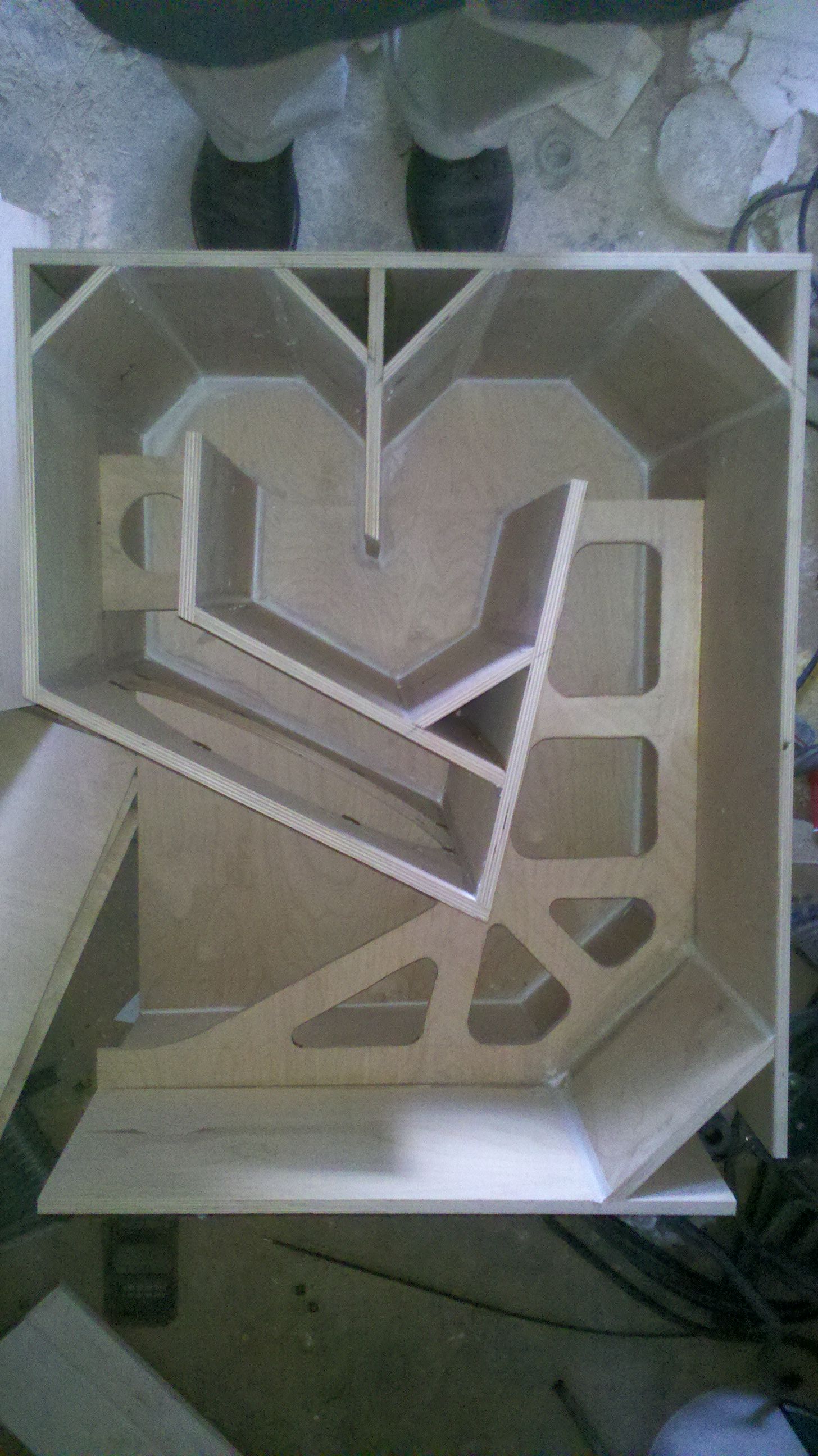
Starting off with the internal structure.
When you have drawn where all the pieces are going to be, it is very easy to pre drill holes for the screws. I don’t think it is necessary to use screws when you glue it together but the assembly gets a lot easier and doesn’t require as many clamps.
Some bracing and “baffle” in place
A simple and easy way (Q&D) to fasten the driver. I don’t think I would recommend this sulotion for permanent use. At least not without proper washer’s…
More bracing.
Time to put the last side on.
I used Polyutherane based glue which I think is excellent for this kind of wood working. It expands and creates nice foam that seals any cracks or bad fitting between the panels. One should be very careful with getting it on the skin because I stains the skin and is impossible to get rid of.
/Forsman
My blogg: DIY Open Source HiFi
I relly apprisiate your work and your willingnes to inspire and teach others, like me.
Here are some pitctures from the building of the Thorn F1. First som cutting of particle board in my back yard.
An externally hosted image should be here but it was not working when we last tested it.
An externally hosted image should be here but it was not working when we last tested it.
I found it pretty useful to do a 1:1 drawing of the horn on one of the horn sides. That made the rest of the build much easier when it comes to fit pieces and drill holes at the correct places.
An externally hosted image should be here but it was not working when we last tested it.
Cutting the hole for the driver.
An externally hosted image should be here but it was not working when we last tested it.
Starting off with the internal structure.
An externally hosted image should be here but it was not working when we last tested it.
When you have drawn where all the pieces are going to be, it is very easy to pre drill holes for the screws. I don’t think it is necessary to use screws when you glue it together but the assembly gets a lot easier and doesn’t require as many clamps.
An externally hosted image should be here but it was not working when we last tested it.
An externally hosted image should be here but it was not working when we last tested it.
Some bracing and “baffle” in place
An externally hosted image should be here but it was not working when we last tested it.
A simple and easy way (Q&D) to fasten the driver. I don’t think I would recommend this sulotion for permanent use. At least not without proper washer’s…
An externally hosted image should be here but it was not working when we last tested it.
More bracing.
An externally hosted image should be here but it was not working when we last tested it.
An externally hosted image should be here but it was not working when we last tested it.
Time to put the last side on.
An externally hosted image should be here but it was not working when we last tested it.
I used Polyutherane based glue which I think is excellent for this kind of wood working. It expands and creates nice foam that seals any cracks or bad fitting between the panels. One should be very careful with getting it on the skin because I stains the skin and is impossible to get rid of.
/Forsman
My blogg: DIY Open Source HiFi
Hi Forsman
Nice build. I have never tried this kind of build, but in traditional QW damping where the presasure is highest (the closed end) is most efficient. Just a thought.
Hi from
Bjorn
Nice build. I have never tried this kind of build, but in traditional QW damping where the presasure is highest (the closed end) is most efficient. Just a thought.
Hi from
Bjorn
Hi Forsman,
Good to see someone experimenting with the pressure zones in a TH. I also like the double braces to increase the stiffness of the enclosure. All TH's have their difficulty at full wavelength between S1 and S4 (distance between driver centres at both sides). For your Thorn F1 the distance S1-S4 is 2.12m, which relates to 162Hz (full WL) based on your HornResp inputs.
You could experiment with 'cone volume correction' and 'corner volume correction' to bring the actual build more closely to what you have simmed in HornResp, which could help to improve the area at the dip. Both corrections are located at or near your pressure minimums of the problem area.
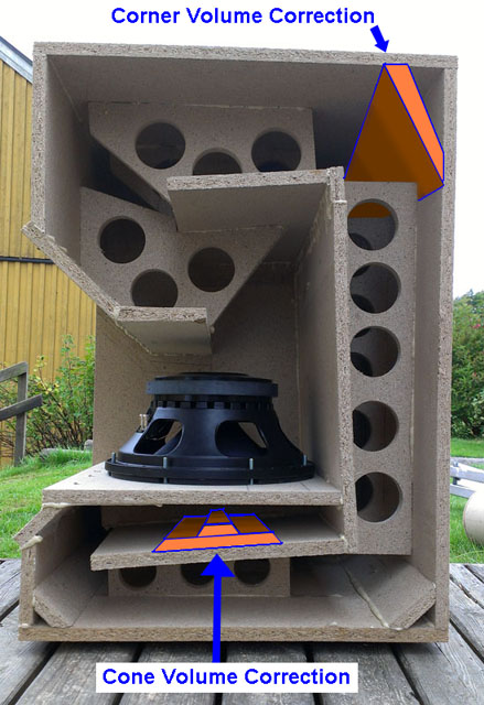
Last edited:
Hi Djim and Björn
Thanks for your input!
I have been thinking a lot about what way to go, either try to learn how to make the build measure as close to the simulation as possible or to learn what effect a certain folding has on the measured response. The two options are of cause closely interlinked but have different implications to how I should work. Personally I think I am more interested in the effects the folding has on the measured response in comparison to simulation. It seems like a more practicable way from my point of view mostly because my flawed understanding for some of the mathematics, but on the other hand, I am eager to learn…
Your thoughts on cone- and corner correction are very interesting.
Martinssons THAM 15 MKII shows less dips at the critical frequency (full wavelength between S1 and S4) with corner reflectors at the end of the horn. I am aware of that the comparison might be flawed because there are different drivers used in the cabinets.
NoDestiny have showed contradictory results with his build of Jbells Single sheet TH challenge where the dips got worse with reflectors. That design has reflectors all way through the pipe and thus in the beginning of the horn path too. My design has reflectors at the beginning of the horn, just as NoDestinys build, and do also show deeper dips than the simulation suggest. Maybe this is far-fetched but I am curious if it could be so that corner reflectors in the beginning of the horn in some way enhances the dips at critical frequency earlier mentioned?
Martinsson's Blog - Showdown in Stenungsund (THAM 15 & MKII proposal)


NoDestinys build of Jbells Single sheet TH challenge
I'll get back the damping issue, that you Björn suggested, later.
Kindest regards
/Forsman
my blogg: DIY Open Source HiFi
Thanks for your input!
I have been thinking a lot about what way to go, either try to learn how to make the build measure as close to the simulation as possible or to learn what effect a certain folding has on the measured response. The two options are of cause closely interlinked but have different implications to how I should work. Personally I think I am more interested in the effects the folding has on the measured response in comparison to simulation. It seems like a more practicable way from my point of view mostly because my flawed understanding for some of the mathematics, but on the other hand, I am eager to learn…
Your thoughts on cone- and corner correction are very interesting.
Martinssons THAM 15 MKII shows less dips at the critical frequency (full wavelength between S1 and S4) with corner reflectors at the end of the horn. I am aware of that the comparison might be flawed because there are different drivers used in the cabinets.
NoDestiny have showed contradictory results with his build of Jbells Single sheet TH challenge where the dips got worse with reflectors. That design has reflectors all way through the pipe and thus in the beginning of the horn path too. My design has reflectors at the beginning of the horn, just as NoDestinys build, and do also show deeper dips than the simulation suggest. Maybe this is far-fetched but I am curious if it could be so that corner reflectors in the beginning of the horn in some way enhances the dips at critical frequency earlier mentioned?
Martinsson's Blog - Showdown in Stenungsund (THAM 15 & MKII proposal)
NoDestinys build of Jbells Single sheet TH challenge
I'll get back the damping issue, that you Björn suggested, later.
Kindest regards
/Forsman
my blogg: DIY Open Source HiFi
Last edited:
Nice work there. That's a pretty smart way of getting an extra fold into the THAM design!
I wouldn't bother with the corner reflectors - they do nothing at bass frequencies and are likely to make matters worse.
Have a look for "Dog food duct" for another possible way of reducing the first major frequency response dip that worked for my POC TH.
Did you take an impedance response measurement? Comparing that to the HornResp prediction can perhaps provide some guidance as to where your completed product differs from the simulation.
Forsman,Let’s drill some holes and do some measuring.
What a great measurement idea!
So interesting to see the progression of amplitude, phase, and frequency response in your TH.
By half way through the horn, looks like things don't change much other than in the upper out of band frequencies, other than inverse distance amplitude reduction.
Seeing that the throat SPL is some 25 dB above the mouth pressures gives some real insight to the problems encountered with cones not strong enough for the task.
155 dB is also enough to get in to levels of air non-linearity.
Was the microphone flush with the cabinet wall, or some distance in towards the center of the horn?
If flush, the throat SPL may be be even higher.
It would be interesting to see a measurement with the mic directly at the cone center.
Did both the 10 cm and 20 cm measurements get lost?
What was the approximate SPL of the "0 dB" line on the graphs?
Thanks,
Art
Attachments

Thanks Brian and weltersys!
This kind of fold also enables you to make L45 a bit longer if dezired. In my case I like that because I think it helps filling out the 150 Hz dip a bit and extends the bass response a few Hz.
The Dog Food Duct is interesting. I have tried something similar but not with the same great result as you have. I will get back to that experiment soon.
The microphone wasent flush. I have inserted it about 7 cm.
I shall see if I can get the measurements from pos. 10 and 20 Cm from S1. Do You want me to take a measure at the cone center position too?
I am not sure what the "0 db" level is unfortenutley.
An idea to address the dip at approx. 150 Hz is to damp the horn at the position where the pressure minimum is for the frequency. Looking at the measurements that would be at a position about 120 cm from S1. I figure that where the pressure is low the air speed is high and therefore the right place to apply some damping.
I did drill three holes in the back of the horn, placed 80 g of polyester fiber wool there and sealed it up properly.
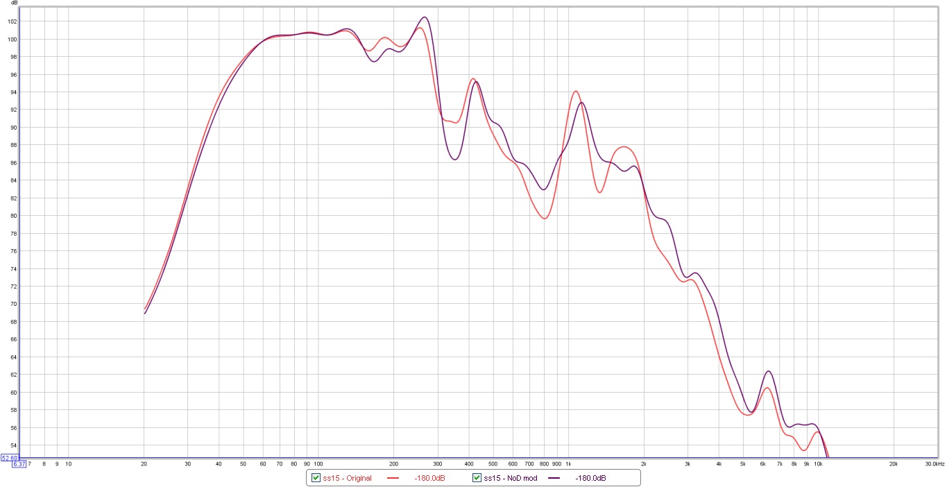
The measurements are made in the middle of the mouth of the horn. I have zoomed in quite a bit to get better resolution of the SPL response graphically.
Green curve is the original horn without any damping and red curve is with 80 g och polyester wool damping.
Well that much damping eats a lot of the bass response and makes the dip at 150 Hz even worse!
Reducing the amount of damping by half and a new measurement.
Not much better. The peaks are somewhat lower, so are also the dips but not to the same extent and I am loosing bass.
I am a bit surprised of this result. I really thought that damping at the pressure minimum would have positive effects on the 150 Hz dip.
It does look much better when I zoom out and apply some smoothing... 😉
Kind regards
/Fredrik
my blogg
This kind of fold also enables you to make L45 a bit longer if dezired. In my case I like that because I think it helps filling out the 150 Hz dip a bit and extends the bass response a few Hz.
The Dog Food Duct is interesting. I have tried something similar but not with the same great result as you have. I will get back to that experiment soon.
The microphone wasent flush. I have inserted it about 7 cm.
I shall see if I can get the measurements from pos. 10 and 20 Cm from S1. Do You want me to take a measure at the cone center position too?
I am not sure what the "0 db" level is unfortenutley.
An idea to address the dip at approx. 150 Hz is to damp the horn at the position where the pressure minimum is for the frequency. Looking at the measurements that would be at a position about 120 cm from S1. I figure that where the pressure is low the air speed is high and therefore the right place to apply some damping.
I did drill three holes in the back of the horn, placed 80 g of polyester fiber wool there and sealed it up properly.
An externally hosted image should be here but it was not working when we last tested it.
The measurements are made in the middle of the mouth of the horn. I have zoomed in quite a bit to get better resolution of the SPL response graphically.
Green curve is the original horn without any damping and red curve is with 80 g och polyester wool damping.
An externally hosted image should be here but it was not working when we last tested it.
Well that much damping eats a lot of the bass response and makes the dip at 150 Hz even worse!
Reducing the amount of damping by half and a new measurement.
An externally hosted image should be here but it was not working when we last tested it.
Not much better. The peaks are somewhat lower, so are also the dips but not to the same extent and I am loosing bass.
I am a bit surprised of this result. I really thought that damping at the pressure minimum would have positive effects on the 150 Hz dip.
It does look much better when I zoom out and apply some smoothing... 😉
An externally hosted image should be here but it was not working when we last tested it.
Kind regards
/Fredrik
my blogg
Last edited:
Fredrik,The microphone wasent flush. I have inserted it about 7 cm.
I shall see if I can get the measurements from pos. 10 and 20 Cm from S1. Do You want me to take a measure at the cone center position too?
I am not sure what the "0 db" level is unfortenutley.
I did drill three holes in the back of the horn, placed 80 g of polyester fiber wool there and sealed it up properly.
Well that much damping eats a lot of the bass response and makes the dip at 150 Hz even worse!
I am a bit surprised of this result. I really thought that damping at the pressure minimum would have positive effects on the 150 Hz dip.
A center cone measurement would be interesting compared to pos. 10 and 20 Cm from S1if you can get the mic in that far.
Do you have a dB meter you can compare the measurements to ?
Your cabinet response looks fairly smooth, and the rising response around 100 Hz can easily be equalized out, which ends up giving a lot more headroom in an frequency range that gets pounded on with vigor in most pop music.
I much prefer the extra headroom over the loss that damping always presents- if you want flat response, might as well just make a bass reflex cabinet 😉.
Art
Art, no swearing in my thread please... 😉- if you want flat response, might as well just make a bass reflex cabinet 😉.
/FF
Art, no swearing in my thread please... 😉- if you want flat response, might as well just make a bass reflex cabinet 😉.
/FF
hehe, Forsman , i got that .....
So i have a question ... It looks like a Pseudo "DFD" was tried with this TH but its not like the one that Brian Steele came up with because it was made of damping material instead of a constriction right?
If i understood correctly the method for finding the areas to place this damping material was also different because Brian found his location by searching for a pressure maximum at the frequency of the dip he wanted to fill in ....
Have you considered trying that? It might fill in that first big dip and give you useable response right up to about 260hz , because as it is your second dip doesn't seem to be that bad at all really in the chart that you posted.. Not nearly as bad as in the simulation .. 🙂
I am very sorry for my multiple posts above. I got outsmarted by my phone and somehow posted it several times. Apologies.
/mvhff
/mvhff
Yes Matthew, it is as pseudo “DFD”.
I haven’t come that far yet that I have tried these ideas at the pressure maximum. I think it absolutely is worth trying. Looking at the phase response I don’t think this horn is usable above 150 Hz as it looks like now. I am curious though what would happen with the phase response if I could tame the SPL. If I get a controlled SPL will that automatically give me a controlled phase response then?
Brian, your “Dog Food Duct” is a very interesting idea. I have tried something similar but I didn’t get the same good result as you did.
I am still working at the pressure minimum for the 150 Hz dip, which might be all wrong.
Let’s take the out the damping and construct a couple of paddles to fit in the holes, by doing so I obstruct approximately half of the horn area. The bends seam to help create standing waves in the horn. By cutting the cross section by half I hoped to induce the same effect as a bend tend to do.
Unfortunately my idea didn’t work at all.
Have I cut the cross section down too little? Or am I trying to address the problem at the wrong place in the horn, should I maybe aim for th pressure maximum at 150 Hz instead?
/Forsman
I haven’t come that far yet that I have tried these ideas at the pressure maximum. I think it absolutely is worth trying. Looking at the phase response I don’t think this horn is usable above 150 Hz as it looks like now. I am curious though what would happen with the phase response if I could tame the SPL. If I get a controlled SPL will that automatically give me a controlled phase response then?
Brian, your “Dog Food Duct” is a very interesting idea. I have tried something similar but I didn’t get the same good result as you did.
I am still working at the pressure minimum for the 150 Hz dip, which might be all wrong.
Let’s take the out the damping and construct a couple of paddles to fit in the holes, by doing so I obstruct approximately half of the horn area. The bends seam to help create standing waves in the horn. By cutting the cross section by half I hoped to induce the same effect as a bend tend to do.
An externally hosted image should be here but it was not working when we last tested it.
An externally hosted image should be here but it was not working when we last tested it.
An externally hosted image should be here but it was not working when we last tested it.
An externally hosted image should be here but it was not working when we last tested it.
Unfortunately my idea didn’t work at all.
Have I cut the cross section down too little? Or am I trying to address the problem at the wrong place in the horn, should I maybe aim for th pressure maximum at 150 Hz instead?
/Forsman
Greetings Forsman,
I haven't had a chance to go through all your data yet but I just wanted to thank you for your fantastic contribution to the diyAudio community. Your in depth investigation will no doubt help many individuals, myself included, refine their TH designs/builds.
Thank you for sharing the results of your time, energy, and resources spent on this.
Keep up the good work.
-Matt
Forsman , As Mattlong8 said above, thank you ... I commend your experimental efforts and scientific spirit!
And yes , I would give the 150hz pressure maximum a shot .... If i understand Brian's work properly then i think he found the general location by sending a microphone into the horn while playing a sine wave at the target frequency (in this case 150hz) ..... Look for the point where 150hz is at it's loudest, which was roughly 1/3rd of the way up the pipe starting from the mouth of the horn...
Once you have found your location then you can adjust the panel back and forth a few centimeters until you get it perfectly dialed in.. You may find that the panel will end up being slightly deeper inside of the pipe than you initially measured since the constriction shifts the fundamental resonance down by a few hertz (4hz in Brian's POC2)..
Forsman , As Mattlong8 said above, thank you ... I commend your experimental efforts and scientific spirit!
And yes , I would give the 150hz pressure maximum a shot .... If i understand Brian's work properly then i think he found the general location by sending a microphone into the horn while playing a sine wave at the target frequency (in this case 150hz) ..... Look for the point where 150hz is at it's loudest, which was roughly 1/3rd of the way up the pipe starting from the mouth of the horn...
It's close. I used an RTA and some pink noise, and snaked the mic up the horn until I found the point where the notch disappeared from the frequency response. I then messed around with various constrictions until I found one that seemed to produce a decent result at the horn's mouth. It's possible it can be optimized even further, or I was very lucky getting the result that I did 🙂.
The DFD can be simulated in AkaBak (check my thread), which can take some of the guesswork out. But yes, the position of the panel is very important. Shifting it back and forth just a few cm made a HUGE difference in the response around the notch area. Maybe I was very lucky that I got pretty good results just there's a bend in the horn.
The experimentation did leave me wondering what the effect of multiple DFDs might be 🙂.
ahhh ok, pink noise ...... Cool ..... That makes sense.. I need to learn to pay closer attention to detail when i read 
Brian, your DFD and Stuffed Tapped Pipes are awesome demonstrations of "out-of-the-box" thinking and i really admire that sort of pioneering bravery ... You've come up with some useful innovations that could be applied to other cabinets ..
I'm a little confused on the microphone part though, i thought you would look for a peak (pressure maximum) with the microphone as you are moving it down the pipe ....
I was going by something you said in the THAM15 discussion ...
" The effect would significantly reduce, if not disappear, if I moved the obstruction caused by the cards only a inch or two forwards or backwards in the pipe. I also placed the mic *in* the pipe in that location, and set TrueRTA to Rel mode, the graph started to show a peaked response around the same frequencies that the notch appeared in the tapped-pipe's response curve."
http://www.diyaudio.com/forums/subwoofers/175658-tham15-compact-15-tapped-horn-18.html#post2448729
- Status
- Not open for further replies.
- Home
- Loudspeakers
- Subwoofers
- Thorn F1 - a learning experiance with Tapped Horn