I have two Soundsplinter Rl-p18's in an isobaric configuration in a sealed box
wired series/series. Each speaker has dual 4 ohm voice coils which when in
series gives Z = 8 ohms and Le = 4.34 mH, so for the complete sub, Z = 16
ohms and Le = 8.68 mH. I'm using a bridged Crest Cpx-1500 to power this,
which has a minimum bridged load of 8 ohms. The Crest is fed a low pass
80Hz LR signal.
I am considering getting an amp with a lower bridged impedance capability.
Here are the sub impedance/inductance options:
1) series/parallel: Z = 4 ohms, Le = 2.17mH.
2) parallel/parallel: Z = 1 ohm, Le = 0.5425mH.
I've read the transient response would be improved from an inductance reduction of 8.68mH to 2.17mH. But besides not having
many choices of an amp to deliver a 1 ohm bridged load into 500W
(maybe Hypex?), would it be worth the effort to reduce it to 0.5425mH?
Last edited:
So what you're implying is that reducing the Z/Le ratio would involve
replacing the existing speakers, i.e.; it is fixed. What I really want to
know is considering the Soundsplinter Rl-p18's high inductance, would an
alternative with a lower inductance have a more accurate sound? Currently,
there is a peak in the 80Hz area which I have almost EQ'd out. I am
assuming this is caused by the high inductance of the speakers. The sub
crosses over to Altec A7's, and when run with no sub, there is no peak.
It should be easy enough to see what the effect would be. Un-bridge the amplifier and run one channel to each driver that's wired in series for 8 ohms.
That's probably how I'd have them driven anyway.
Edit: As far as lower inductance drivers, remember that the inductance comes from the driver's coil. It works just like a coil that one might use in a crossover. The larger and beefier the coil is, the more inductance it's going to have. Going to a lower inductance speaker, means you'd probably end up with one that had a smaller coil.
The beefier the woofer's motor structure, the more inductance it usually has.
Last edited:
Is the peak at ~80Hz in the SPL or in the impedance plot?
The speaker will have a resonance and the enclosure design is there to minimize the effects of it as best it can. This is a mechanical resonance, not electrical.
To get an electrical resonance at 80 Hz with 4.34mH you would need 912uF.
I don't think there is that much C in the voice coil.
The speaker will have a resonance and the enclosure design is there to minimize the effects of it as best it can. This is a mechanical resonance, not electrical.
To get an electrical resonance at 80 Hz with 4.34mH you would need 912uF.
I don't think there is that much C in the voice coil.
The 80Hz is a SPL peak. The sealed part of the box is approximately 4.0 cu.
ft. This is in an isobaric "clamshell" configuration. The box itself is two 4.0
cu. ft. chambers, one sealed and the other with a 14"X22" "port". The
drivers mount on the center line between the two chambers. I figured
the huge port was like having no containment on the outer driver. Could
this be tuning the box? The calculated F3 of the box is in the low thirties,
and low frequency extension is very good.
So consensus here is that high inductance is not necessarily a bad thing,
and is a byproduct of building a driver with low frequency capability.
The 80Hz is a SPL peak. The sealed part of the box is approximately 4.0 cu.
ft. This is in an isobaric "clamshell" configuration. The box itself is two 4.0
cu. ft. chambers, one sealed and the other with a 14"X22" "port". The
drivers mount on the center line between the two chambers. I figured
the huge port was like having no containment on the outer driver. Could
this be tuning the box? The calculated F3 of the box is in the low thirties,
and low frequency extension is very good.
So consensus here is that high inductance is not necessarily a bad thing,
and is a byproduct of building a driver with low frequency capability.
Hi Bruse,
Am I right that the 'clamshell' drivers is in a 8 cu.ft box where 4 cu.ft is closed and the front-box is also 4 cu.ft equipped with a port system= 14" diameter,22" long...if so I couldn't design this using HR showing an acceptable FR.
I may be wrong but I guess you have used the driver parameters in a way the returned odd box dimensions.
Here is another example using one of your drivers in a box that IMO would be hard to beat SQ performance wise and is IMO capable to wreck your walls if placed in an ordinary living room It's an OD_T-TQWT of-course, a kind of pointsource quarter-wave BP box that should be folded at least two times.
b
")
PS: Why not put your design dimensions into HR and post here for (eventual help and ) examination?
Attachments
consider that le is not fixed,it risez to lower freq.
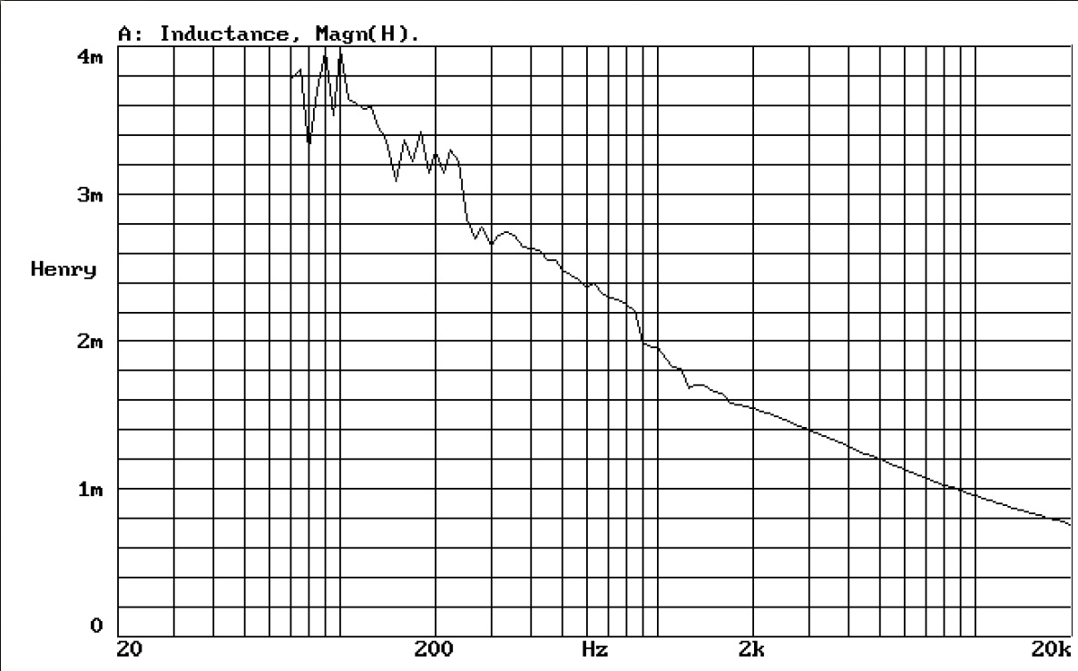
I don't understand this. I always thought that the inductance value is fixed (Henry) and that the apparent resistance changed in function of frequency.
In the graphic the Henry value changes with frequency
If this is true, how can a coil be labeled having a fixed value of xx mH?
Bjorno,
The 14"X22" opening is not really a "port". The box is just basically one
4 cu. ft. sealed enclosure in an isobaric configuration. The 4 cu. ft. over
the outer driver is a superstructure to protect the driver. The 14"X22" is
an absent panel on one side of the box. Additionally, an 6"X4" piece is
missing on the other side of box in the same chamber. The purpose of
all this was to minimize any effect the outer 4 cu. ft. has on the driver.
I don't believe it affects the low frequency.
I realize I am not using the full capability of the driver. I wanted a
compact enclosure with good sound and easy manufacture. At one time
I did consider a horn sub, but due to past experience with a Klipsch
Lascala, I now time align all drivers physically. I only have one Dac in
my system, and digital time correction external to a computer would
void this. If I did the time correction on a computer, most of my
electronics would need to change.
Last edited:
Bjorno,
The 14"X22" opening is not really a "port". The box is just basically one
4 cu. ft. sealed enclosure in an isobaric configuration. The 4 cu. ft. over
the outer driver is a superstructure to protect the driver. The 14"X22" is
an absent panel on one side of the box. Additionally, an 6"X4" piece is
missing on the other side of box in the same chamber. The purpose of
all this was to minimize any effect the outer 4 cu. ft. has on the driver.
I don't believe it affects the low frequency.
I realize I am not using the full capability of the driver. I wanted a
compact enclosure with good sound and easy manufacture. At one time
I did consider a horn sub, but due to past experience with a Klipsch
Lascala, I now time align all drivers physically. I only have one Dac in
my system, and digital time correction external to a computer would
void this. If I did the time correction on a computer, most of my
electronics would need to change.
If B has a suggestion for that driver, you'd probably be much farther ahead just building it and thanking him later
When a driver is "labeled" as having x.x mH of inductance, it is not to be taken as meaning that it is a fixed value. It is usually measured at 1 kHz. Some manuals say so, some don't. Think of inductance as a LPF. The more inductance, the earlier this "filter" comes on.
Also, inductance is not always a byproduct of a driver with low-frequency capability. My JBL W10GTi has 17mm of Xmax and inductance of less than 1 with DCR of 3.8. But this one is the exception, rather than the norm.
Also, inductance is not always a byproduct of a driver with low-frequency capability. My JBL W10GTi has 17mm of Xmax and inductance of less than 1 with DCR of 3.8. But this one is the exception, rather than the norm.
@ OscarS: Thank you.
Maybe that's the explanation I'm searching for in another thread. Would you mind having a look at it please?
measurement
Maybe that's the explanation I'm searching for in another thread. Would you mind having a look at it please?
measurement
The 4 cu. ft. over the outer driver is a "something" (whether you want to call it a port, a horn stub, a dog house or whateverBjorno,
The 14"X22" opening is not really a "port". The box is just basically one
4 cu. ft. sealed enclosure in an isobaric configuration. The 4 cu. ft. over
the outer driver is a superstructure to protect the driver.
) which easily could account for an 80 Hz peak.That configuration is similar to an open back guitar cabinet, which is actually a very high Fb ported cabinet.
As mentioned before, modeling your driver/cabinet in Hornresp would be useful, your problem seems cabinet related, not an inductance problem.
Art
Last edited:
I don't understand this. I always thought that the inductance value is fixed (Henry) and that the apparent resistance changed in function of frequency.
In the graphic the Henry value changes with frequency
If this is true, how can a coil be labeled having a fixed value of xx mH?
The factors contributing to the inductance value include number of voice coil turns squared but also the proximity of the Iron and the permeability of the magnet assembly. It is an Iron core inductor.
Not only does the inductance change with frequency (probably due to changes in the Iron and magnet permeability vs. frequency), it changes with speaker amplitude and instantaneously with voice coil position as it moves in and out of the Iron gap.
.
As confusing as labeling a speaker with a certain impedance that changes by a factor of 20 throughout it's operating range.
Dave
- Status
- This old topic is closed. If you want to reopen this topic, contact a moderator using the "Report Post" button.
- Home
- Loudspeakers
- Subwoofers
- Subwoofer Inductance Reduction