Kicker 08S15L74 Double Fold T-TQWT Build
I'm building my 1st T-TQWT. I want to do a double fold to keep the box as square as possible. I used Volvotreter's pdf to design the folds. My question is how do you fellas maintain the correct board angles and have a constant decreasing flare (or for you TH guys, increasing flare) minus any corner deflectors? When I follow the 45* procedure, the top right hand corner increases in flare instead of decreasing in flare.
I got the 3 corner numbers from drawing this spreadsheet on MDF.
Last edited:
..My question is how do you fellas maintain the correct board angles and have a constant decreasing flare..
Hi,
The horizontal piece labeled 18.19 x 16 should IMO be attached at the ends to 2 perpendicular mounted vertical dividers where one of the latter is labeled 15.69 x 16 in your picture.
I would take an much easier approach to fold by designing a T-TQWP instead. The only drawback I can see is the need for an additional ~23L of volume.
b 🙂
Attachments

I'm building my 1st T-TQWT. I want to do a double fold to keep the box as square as possible.
Try the folding scheme here - The Subwoofer DIY Page v1.1 - Projects : A "Proof of Concept" tapped pipe - introduction
By varying the position of two internal dividers, you can get a T-QWT, T-QWP or even a TH.
I was hoping you would respond bjorno! Thank you! The inner top piece is drawn perpendicular to the speaker plate and the inner rear piece. It's easier to leave the inner top piece at 6" from the outer top piece in Excel. That's why I have all the corner dimensions labeled so you can visualize the inner and outer top pieces are not parallel to each other. I can't use 600cm2 for a TQWP. The Kicker 08S15L74 has an 8.6875" mounting depth. I did design a 825.8cm2 (8" x16") TQWP, but its 2 feet longer to get the response I want for HT.


Try the folding scheme here - The Subwoofer DIY Page v1.1 - Projects : A "Proof of Concept" tapped pipe** - introduction
By varying the position of two internal dividers, you can get a T-QWT, T-QWP or even a TH.
Thank you for responding Brian! In this shot, the hole on the right of the speaker is the half way point of the horn, in my case would be 7" x 16"?
Thank you for responding Brian! In this shot, the hole on the right of the speaker is the half way point of the horn, in my case would be 7" x 16"?
Hi BP1Fanatic,
I use an iterative process based on the data from the Hornresp input screen. It's basically the same process I used BC (before computers):
Use a cad program (in my case AutoCAD) because of the build in measurement capabilities. Example for a TH or a T-TQWT:
1. Draw a horizontal line representing the total length of the horn path.
2. Draw a vertical line for S1 on one end of the horizontal line, and another for S4 on the other end; I arrive at the length of these lines by dividing the respective area values from Hornresp by the choosen internal width of the box.
3. Connect the free ends of the vertical lines. Then I use the dimensioning command to give me the angle between the original horizontal line, and the line connecting the free ends of the vertical lines; this is the taper of the duct.
4. From your original idea of the layout, start drawing the layout using the taper angle from 3. above, and the duct heights derived from the S1/S2 values from Hornresp for the throat end, and from the mouth end the S4/S3 values.
5. When you have the first (almost by definition wrong) drawing, use Soho54's method for drawing cross-section lines into the duct path (the lines called S1/S2/1/2/3... in the example).
6. Then connect the midpoints of these lines (all the way from S1 to S4) with a line representing the total duct length. You can now compare the total length from the first attempt at a layout drawing and the total length from Hornresp, and adjust the drawing until the two values are close.
7. Now you're ready to work through the path of the duct by - for example -connecting the midpoints of the cross-section lines from S1 to #1 (the first change of direction). In AutoCAD you can use the "List" command to give you the length of this line. Transfer this length to your original horizontal line from 1. above, and draw a vertical long enough to intersect the line you drew in 3. above. The length of the vertical line from the horizontal to the taper line is the duct height at this point. You can now position the divider boards respectively. Now, move on to #2, etc....
8. When you're done with that you will have to adjust the layout to correct for length and cross-sectional errors.
It will obviously take multiple iterations to get close, and for a given design a computer solution is the way to go. I haven't kept up with Brian Steele's and Soho54's spreadsheet work on that subject.
It helps to have a number of drawings for different layouts as a starting point, but it sounds worse than it is. By the way, the top horizontal boards in your drawing (31.00x16.00 and 18.19x16.00) should not be parallel.
Regards,
Attachments

Last edited:
Hi,
The horizontal piece labeled 18.19 x 16 should IMO be attached at the ends to 2 perpendicular mounted vertical dividers where one of the latter is labeled 15.69 x 16 in your picture.
I would take an much easier approach to fold by designing a T-TQWP instead. The only drawback I can see is the need for an additional ~23L of volume.
b 🙂
Hi Bjorno,
You assisted me with a horn for my B139-how do you get the schematic diagram to "show" you horn sections and final horn as in that picture? I think* I've worked mine out using graph paper and scissors-a way in HR would be far preferable!
*I'm sure that my horn will actually end up losing volume/length and not output as your model suggests
OP-sorry for jumping on your thread-but as I'm having the same issues this could be helpful to both of us!
Hi BP1Fanatic,
I use an iterative process based on the data from the Hornresp input screen. It's basically the same process I used BC (before computers):
Use a cad program (in my case AutoCAD) because of the build in measurement capabilities. Example for a TH or a T-TQWT:
1. Draw a horizontal line representing the total length of the horn path.
2. Draw a vertical line for S1 on one end of the horizontal line, and another for S4 on the other end; I arrive at the length of these lines by dividing the respective area values from Hornresp by the choosen internal width of the box.
3. Connect the free ends of the vertical lines. Then I use the dimensioning command to give me the angle between the original horizontal line, and the line connecting the free ends of the vertical lines; this is the taper of the duct.
4. From your original idea of the layout, start drawing the layout using the taper angle from 3. above, and the duct heights derived from the S1/S2 values from Hornresp for the throat end, and from the mouth end the S4/S3 values.
5. When you have the first (almost by definition wrong) drawing, use Soho54's method for drawing cross-section lines into the duct path (the lines called S1/S2/1/2/3... in the example).
6. Then connect the midpoints of these lines (all the way from S1 to S4) with a line representing the total duct length. You can now compare the total length from the first attempt at a layout drawing and the total length from Hornresp, and adjust the drawing until the two values are close.
7. Now you're ready to work through the path of the duct by - for example -connecting the midpoints of the cross-section lines from S1 to #1 (the first change of direction). In AutoCAD you can use the "List" command to give you the length of this line. Transfer this length to your original horizontal line from 1. above, and draw a vertical long enough to intersect the line you drew in 3. above. The length of the vertical line from the horizontal to the taper line is the duct height at this point. You can now position the divider boards respectively. Now, move on to #2, etc....
8. When you're done with that you will have to adjust the layout to correct for length and cross-sectional errors.
It will obviously take multiple iterations to get close, and for a given design a computer solution is the way to go. I haven't kept up with Brian Steele's and Soho54's spreadsheet work on that subject.
It helps to have a number of drawings for different layouts as a starting point, but it sounds worse than it is. By the way, the top horizontal boards in your drawing (31.00x16.00 and 18.19x16.00) should not be parallel.
Regards,
Thank you tb46! Like I said earlier, those top 2 pieces are not parallel in my drawing on mdf. It's just easier to leave them parallel in excel since the top right corner rounds up to 6" & the top left corner rounds down to 6". Notice the different widths stated in each corner.
the top right corner rounds up to 6" & the top left corner rounds down to 6".
I SHOULD have stated, "top LEFT corner rounds up to 6" (5.81 & 5.94) & the top RIGHT corner rounds down to 6" (6.44 & 6.25)." I was rushing, keying from my cellphone, when I posted that statement.
If you have a straight taper all your joints except the baffle board at the mouth will be 90°.
If you settle on a design I can render it out from the hornresp.
If you settle on a design I can render it out from the hornresp.
Thanks Neo! I just got done going thru JBell's SS15 thread. I can't tell if everyone is building post #53 or not. tb46 has pdf's on posts' 63, 74, 82, 228, 250, 430, 581, & 584. They all have pinches like my top right corner. He stated in post 650 that no one has really been able to improve on the original (post 53?). If the pinches in tb46's SS15's are not a performance issue, then I'm not going to worry about mine. I'm going to check out Volvotreter's 30hz TH build again to see if he shows a pinch too since I used his folding scheme. I just realized I mixed him up with William Cowan in post #1. My fault fellas!
P.S. bjorno's TQWP is killer in the thread! I'll take the 10hz over the 5dB's! What a simple build too!
P.S. bjorno's TQWP is killer in the thread! I'll take the 10hz over the 5dB's! What a simple build too!
Last edited:
Turns out Volvotreter went from 9.6 to 9.1 in the top left corner of his 30hz TH pdf. Looks like pinches are not too much of an issue.
http://www.volvotreter.de/downloads/TangBand_W6-1139SC_Horn_Rev_1.pdf
http://www.volvotreter.de/downloads/TangBand_W6-1139SC_Horn_Rev_1.pdf
Last edited:
LOL!!! Please sketch this one instead. Bjorno's TQWP in JBell's SS15 thread is just too nice. This TQWP is a 12 footer. 35.75" x 35.75" x 17.5"...a square enclosure for the L7!!!!


Last edited:


I decided to go with the original 222L T-TQWT in post #1 since I found out I have all the spare wood I need to build it. Here are pics of the pieces drawn out on MDF. I will start making sawdust tomorrow after work.
An externally hosted image should be here but it was not working when we last tested it.
An externally hosted image should be here but it was not working when we last tested it.
An externally hosted image should be here but it was not working when we last tested it.
An externally hosted image should be here but it was not working when we last tested it.
An externally hosted image should be here but it was not working when we last tested it.
An externally hosted image should be here but it was not working when we last tested it.
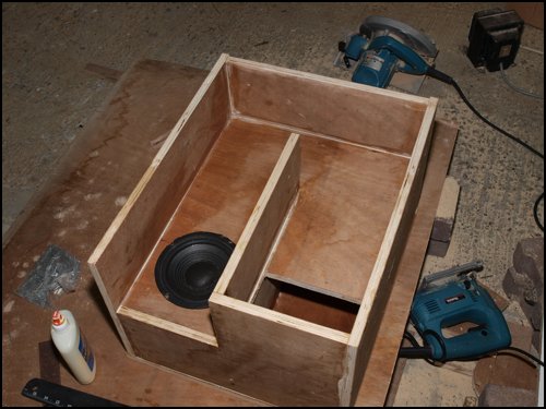
Sawdust made.
An externally hosted image should be here but it was not working when we last tested it.
An externally hosted image should be here but it was not working when we last tested it.
- Status
- Not open for further replies.
- Home
- Loudspeakers
- Subwoofers
- T-TQWT Double Fold Question