From an airflow stand point I also struggle to accept the "sharp corners don't hurt" viewpoint, even if it were true and inaudible. Can you calculate how three turns will affect the tuning? If not corrections of that port could be difficult.
In my world, airflow path bend sums equaling 90° defines a turn, for what ever that's worth.")
In my world, airflow path bend sums equaling 90° defines a turn, for what ever that's worth.
you could run it through hornresp - guess a final impedance measurement will tell how close you got to target http://www.diyaudio.com/forums/subwoofers/180569-modelling-horn-reflex-enclosure-hornresp.html
Yes, I thought so. My instinctive answer to the first question was:
-"but... WHY??!!"
I have no idea what you're really trying to accomplish. If you could explain what your design goals are, then I might be of some help.
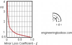
And a prime tip: When you're optimizing for "a certain parameter" when designing a duct, static flow loss coefficients are only good for very small signal simulation. What you're really interested in are the dynamic properties at large-signal levels. And that's quite some way above the static flow resistance harts you linked.
The main difference between duct designs are the levels of support as compared to the in-box air pressures they can sustain before going into totally turbulent mode - i.e almost full blocking /no flow.
What you want to do is to minimize the duct area so that you get the best utilization of the box SPL output. To large port areas demand to long ports - that have other problems like longitudinal standing waves and cross-section effects.
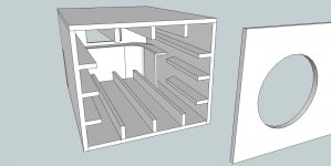
Slit-type ports often have lots of gains to be had from adding thin sectioning walls, dividing the slit into several separate "ports". You need to mind end-point flows, and you loose some few tenths of a dB in small-signal efficiency - but you get a more linear response, and it increases the maximum flow (SPL) before turbulence port blocking occurs.
-"but... WHY??!!"
I have no idea what you're really trying to accomplish. If you could explain what your design goals are, then I might be of some help.
And a prime tip: When you're optimizing for "a certain parameter" when designing a duct, static flow loss coefficients are only good for very small signal simulation. What you're really interested in are the dynamic properties at large-signal levels. And that's quite some way above the static flow resistance harts you linked.
The main difference between duct designs are the levels of support as compared to the in-box air pressures they can sustain before going into totally turbulent mode - i.e almost full blocking /no flow.
What you want to do is to minimize the duct area so that you get the best utilization of the box SPL output. To large port areas demand to long ports - that have other problems like longitudinal standing waves and cross-section effects.
Slit-type ports often have lots of gains to be had from adding thin sectioning walls, dividing the slit into several separate "ports". You need to mind end-point flows, and you loose some few tenths of a dB in small-signal efficiency - but you get a more linear response, and it increases the maximum flow (SPL) before turbulence port blocking occurs.
Yes, I thought so. My instinctive answer to the first question was:
-"but... WHY??!!"
I have no idea what you're really trying to accomplish. If you could explain what your design goals are, then I might be of some help.
And a prime tip: When you're optimizing for "a certain parameter" when designing a duct, static flow loss coefficients are only good for very small signal simulation. What you're really interested in are the dynamic properties at large-signal levels. And that's quite some way above the static flow resistance harts you linked.
The main difference between duct designs are the levels of support as compared to the in-box air pressures they can sustain before going into totally turbulent mode - i.e almost full blocking /no flow.
What you want to do is to minimize the duct area so that you get the best utilization of the box SPL output. To large port areas demand to long ports - that have other problems like longitudinal standing waves and cross-section effects.
Slit-type ports often have lots of gains to be had from adding thin sectioning walls, dividing the slit into several separate "ports". You need to mind end-point flows, and you loose some few tenths of a dB in small-signal efficiency - but you get a more linear response, and it increases the maximum flow (SPL) before turbulence port blocking occurs.
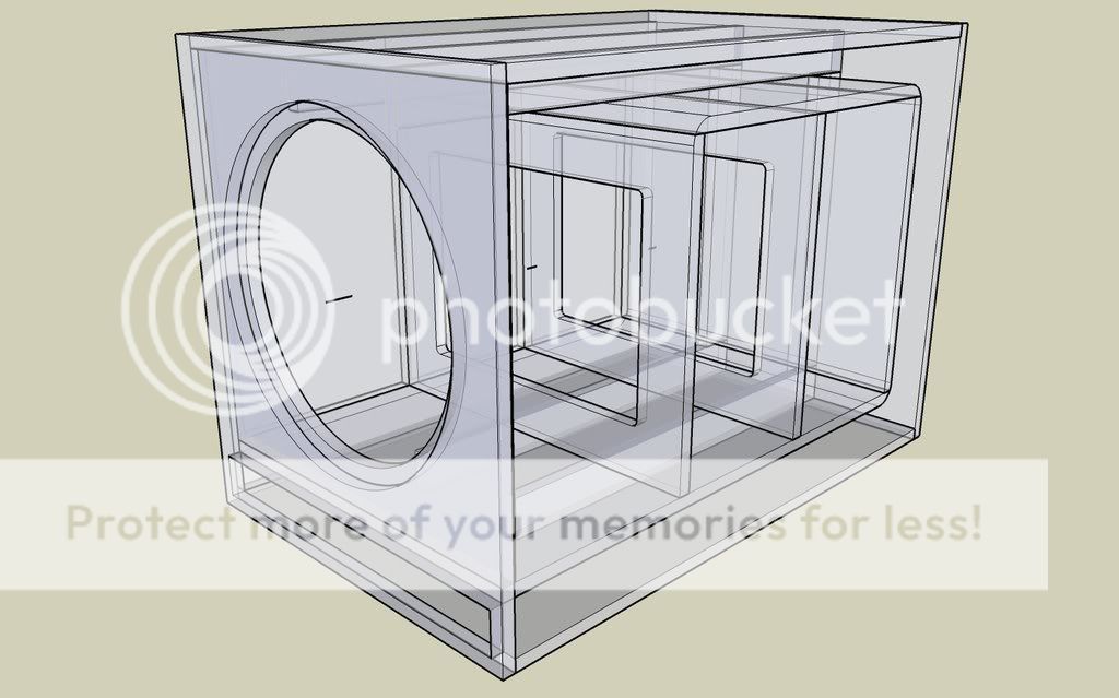
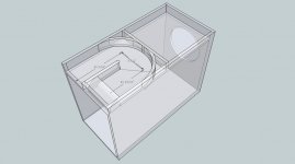
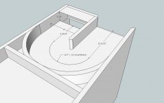
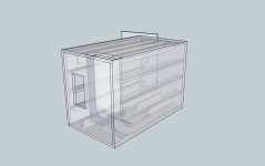
The physics say that's three ports with a summing chamber, which would rase the tuning quite a bit vs one of the same length/combined area.
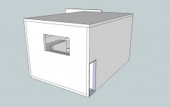
That summing chamber at the port exit is the interesting thing, thanks for sharing. Any measurements taken with that box?
With 1.5" roundovers in the port the tuning is ~12hz IIRC.
I'm curious as to why the dividers would raise the tuning? From my POV the opposite seems logical, the dividers increase surface friction and make the port area smaller? Though at >8" dia "smaller" is relative...
Hey guys, It´s simple see the result is you se HR. It´s also good for BR as NEO Dans CAD shows. Also revbodens is easy to sim. Volume length ans T/S parmeters are needed. though.
Hi Lars,
You make it sound so simple. I'm sure if I had a look through your posts I'd find one that said something like... The sims will get you in the ball park, but only so far...
I'm not aware of any available software that accounts for resistive losses that would be present in my port configuration, are you?
- Status
- This old topic is closed. If you want to reopen this topic, contact a moderator using the "Report Post" button.
- Home
- Loudspeakers
- Subwoofers
- curved slot port design, folding horn guys any thoughts?