One would have to bastardize the spreadsheets severely me thinks, and good luck proving you have done the job correctly. Loads of build iterations would be required.
I'm not aware of any available software that accounts for resistive losses that would be present in my port configuration, are you?
Better check with David McBean.
I guess a so long and low area port isn´t the most suitable though. Once upen a time(79's built a Daline with a long port and KEF B110 narrow port and work OK. What do you think?
Hey guys, It´s simple see the result is you se HR. It´s also good for BR as NEO Dans CAD shows. Also revbodens is easy to sim. Volume length ans T/S parmeters are needed. though.
Just curious theSuede, why "mocka"(Swedish) in your nick?
It's a pun on the homonyms "Swede" as in "Swedish person" and "suede" as in the suede material...
With 1.5" roundovers in the port the tuning is ~12hz IIRC.
I'm curious as to why the dividers would raise the tuning? From my POV the opposite seems logical, the dividers increase surface friction and make the port area smaller? Though at >8" dia "smaller" is relative...
They do raise the tuning a bit, and yes that's pretty counter-instinctive. To understand why you'd have to make a FEM model of the port, and this is quite a lot beyond the scope of this post.
To make a VERY long story at least a bit shorter, to divide a flow area into several smaller areas (and loosing maybe a percent of area in the process) will increase static flow resistance. BUT (!) we're not interested in static flow resistance here. You're designing a resonant port, not a ventilation duct.
To increase the the support area (the amount of "wall area" surrounding the "duct" volume) will increase the laminary percentage of the total duct area, and hence increase the Reynolds value of the port as a whole - if you make all the supports run perfectly aligned with the modeled flow.
Having a very large, unconstricted cross-section area as a "duct" affects how the air reacts when pressurized from one end of the duct. What you WANT is to have all the air inside the duct to act as a single piston of mass, all molecules of air should move perfectly aligned to eachother - like a solid structure, a rod. This gives a perfect loading of the "spring" - the enclosed air in the box.
If the unconstricted area is large (the circular port has the lowest support-to-area ratio of all types), then changes in pressure entering the duct from one end will lose some coherency, as the molecules inside the duct can move in mostly random ways. On a very small level this is a chaotic gas flow resistance, on a larger level it's "turbulence".
Dividing an area into several smaller sub-sections decreases the "free space" in which turbulence can build. The purely static flow resistance will increase by a very small bit, but resistance to turbulence will rise with a considerable margin. This will increase the effective working range of the port considerably by increasing the maximum flow before total port-blocking occurs (a totally turbulent airflow in the duct, or the duct ends). It will also increase the linearity of the port effect, from small signal to large signal.
I don't have much material here to show you here, but one interesting paper that deals with another side of the coin - the termini of the port - can be found here. http://www.aes.org/tmpFiles/elib/20110920/11094.pdf
It's an interesting read even for the non-techy type of person, you can skip most of the techno-babble and read "just the conclusions" in each section:
With 1.5" roundovers in the port the tuning is ~12hz IIRC.
I'm curious as to why the dividers would raise the tuning? From my POV the opposite seems logical, the dividers increase surface friction and make the port area smaller? Though at >8" dia "smaller" is relative...
The dividers split the port into three ports which means you have to divide the Vb by three to calculate the port tuning.
ref: JL Audio - Car Audio Systems
Hey guys, It´s simple see the result is you se HR. It´s also good for BR as NEO Dans CAD shows. Also revbodens is easy to sim. Volume length ans T/S parmeters are needed. though.
ok,
Vb = 5ft^3 with braces and port volume calculated and subtracted.
port 2.5"H x 8"W x 36" L (16.5Hz)
driver http://www.parts-express.com/pdf/295-464s.pdf
I'm not aware of any available software that accounts for resistive losses that would be present in my port configuration, are you?
This calculator includes friction coefficients: PORT Size Calculations and Formulas for WOOFER and Subwoofer BOXES
you'll notice that approaching aperiodic friction coefficients the calculator adjusts accordingly.
This calculator includes friction coefficients: PORT Size Calculations and Formulas for WOOFER and Subwoofer BOXES
you'll notice that approaching aperiodic friction coefficients the calculator adjusts accordingly.
That's the closest sim I've seen yet, but it's still way off.
Dan,
Couldn´t you build and report!
That's what I'm doing, I've built a few variations of my design.
That's what I'm doing, I've built a few variations of my design.
Great! Give an example with the parameters above, would be exciting to see how far HR is from your IRL measured results.
Hey guys,
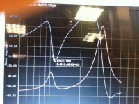
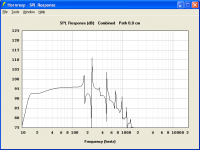
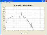
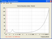
This is what HR says about revbodens box. Placement 1,0*Pi. First with port at the front. The second with port on the rear, path difference 50cm. Third is electrical impedance. Off course no bends and a square or round port.
This is what HR says about revbodens box. Placement 1,0*Pi. First with port at the front. The second with port on the rear, path difference 50cm. Third is electrical impedance. Off course no bends and a square or round port.
Attachments
Last edited:

- Status
- This old topic is closed. If you want to reopen this topic, contact a moderator using the "Report Post" button.
- Home
- Loudspeakers
- Subwoofers
- curved slot port design, folding horn guys any thoughts?