What do block you to learn
LOL! Time, projects and life in general.

I do want to return to Europe someday for holiday.
My father and Stepfather were both U.S. Army and I lived in Nuremberg and Heidelberg as a child.
I didn't even retain any German I learned. As they say, "use it or loss it"
Then I did right, see pictures.
thank you mate.
kees
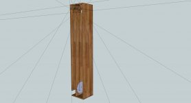
No, your picture is different than mine. In your picture the driver is fully enclosed inside the mouth and the path length of the horn goes past the end of the driver. IF you sawed off the sides and bottom so half the driver basket was truly free then it would be the same as mine.
Draw the centerline path out and you will see what I mean. In my pic the line length stops halfway down the driver basket. In your pic the line length goes past the driver and out through the mouth, it's longer and ensures the driver is completely inside the mouth.
It seems there's some confusion about line length when there is a bend right at the mouth. It's the same length if you put the mouth hole on the side or the bottom. The air has to travel the same distance to get out of the box.
Last edited:
LOL! Time, projects and life in general.
I do want to return to Europe someday for holiday.
My father and Stepfather were both U.S. Army and I lived in Nuremberg and Heidelberg as a child.
I didn't even retain any German I learned. As they say, "use it or loss it"
I can write english in some extent, but do not let me speak, you will fall of your socket. This because I only write, not very good so I go find girl, it is time, a black one in usa? I like this people.
Oke, Neurenberg is militairy stationaired, and maybe if it not go better we get trouble and action there.
Oke that is almost politics and is not alowed.
Somebody here does recognise this on the measurement of the tapped pipe? I get it not right, it flips in fase there because of (standing wave) or what, not yet founded.
But I go to a tapped horn, or even a inverted horn for smaller box lower efficienty.
regards
Attachments

I just might have pulled off my first re-fold.
Going to run this through Hornresp at 13 inch internal depth with two drivers loaded (still the RFP2408's)
A TH with a shimney?
I do folds with sketchup, this do work fine but you have to gess the first start what is not so difficult when you keep mind in the short part of the folds and the rest.
Devide the shorts and the long parts by the number used and start drawning..
Attachments

Last edited:
I just might have pulled off my first re-fold.
If the centerline in that drawing represents the path length, then it will produce incorrect results - the path length for the built subwoofer will be too short. Look up "advanced centerline method" for a better way of estimating path length in a folded 1/4 wave resonator build.
If the centerline in that drawing represents the path length, then it will produce incorrect results - the path length for the built subwoofer will be too short. Look up "advanced centerline method" for a better way of estimating path length in a folded 1/4 wave resonator build.
Thank you, I sure will. It will be interesting to see the results in Hornresp between the two also.
I am posting my work to be examined by others and learn from it.


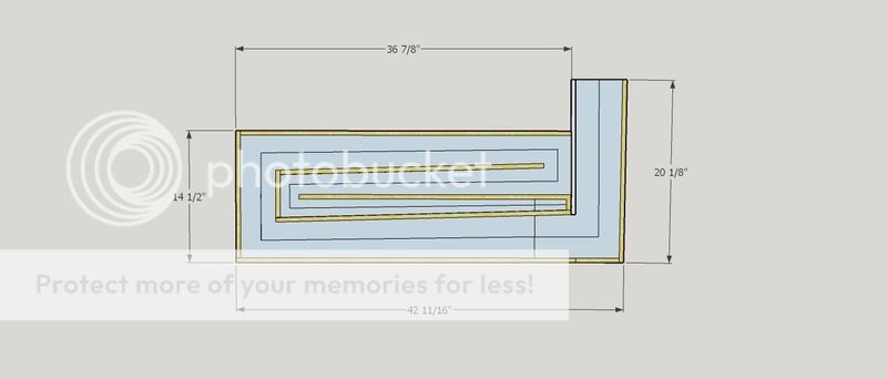
Above is the "Advanced Center Line Method" best I can tell
1st try - ACLM
L12 020.38 to 020.38 (unchanged)
L23 314.61 to 315.08 (0.47 cm longer)
L34 071.25 to 069.53 (1.72 cm shorter)
In the above model L34 has been shortened to 62.5 cm
S1 and S2 are longer now to fit two inline drivers.
I'm still thinking of ways to turn this cabinet into a push/pull configuration.
I attached the Hornresp text file
Still cannot figure out how to post the input and acoustic power charts from Hornresp. LOL
Attachments
Last edited:
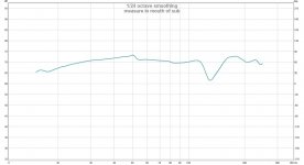
I increased the mouth size to 1090cm2
Why, mostly because the blow though hole from my bed to my cab is 14"x14" (35.56cm), already.
If I am correct in my segment placement in the model then the simulation yields....
-efficiency increased slightly
-F3 increased slightly
- diaphragm displacement decreased slightly
I just want to be sure I am simulating it correctly in Hornresp.
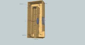
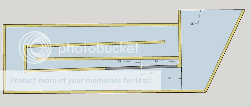
In my SketchUp model below I used these as my segments (S1-S5) in Hornresp
I welcome any and all input.
Why, mostly because the blow though hole from my bed to my cab is 14"x14" (35.56cm), already.
If I am correct in my segment placement in the model then the simulation yields....
-efficiency increased slightly
-F3 increased slightly
- diaphragm displacement decreased slightly
I just want to be sure I am simulating it correctly in Hornresp.
In my SketchUp model below I used these as my segments (S1-S5) in Hornresp

I welcome any and all input.
Last edited:
I increased the mouth size to 1090cm2
Why, mostly because the blow though hole from my bed to my cab is 14"x14" (35.56cm), already.
If you're going to widen the mouth, I suggest also looking at redoing the folding so the driver ends up in the widened section, rather than where you have it now. This will allow you to be able to access the driver directly (through the hole) rather than having to add an "access hatch" to your build.

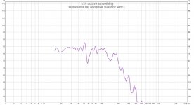
Here is the input information and frequency response plot for the model above. (POST #91)
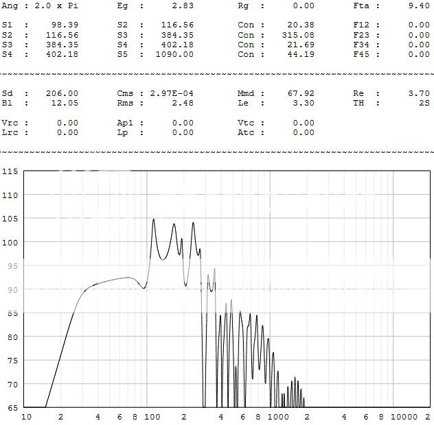
You've got a 15dB peak in out of band noise just above this TH's passband. That's not something I'd be inclined to build.
If you're going to widen the mouth, I suggest also looking at redoing the folding so the driver ends up in the widened section, rather than where you have it now. This will allow you to be able to access the driver directly (through the hole) rather than having to add an "access hatch" to your build.
I am trying to work on that.
But I'm getting confused.
Assuming the design above is correct as far as S1-S5 markings.
If I moved the drivers closer to the mouth L45 cannot be, It has to be L34.
Don't worry, I have not forgot about bracing. Just not to that point yet. lol
You've got a 15dB peak in out of band noise just above this TH's passband. That's not something I'd be inclined to build.
Back to the drawing board. LOLYour right, there is no way that will work well. My sub EQ is +/- 6dB and .5-2.0 Q
Last edited:
You've got a 15dB peak in out of band noise just above this TH's passband. That's not something I'd be inclined to build.
I can tame that peak by filling segment 1 100% with 7000 mks Rayls of stuffing in Hornresp.
With a little research I found that an 89mm fiberglass batt can be found in the 6000 mks rayls range.
Is this even a viable option?
How about a tuned resonator pipe in the throat? 50mm x 850mm using polyfill to adjust Q
Last edited:
I can tame that peak by filling segment 1 100% with 7000 mks Rayls of stuffing in Hornresp.
With a little research I found that an 89mm fiberglass batt can be found in the 6000 mks rayls range.
Is this even a viable option?
How about a tuned resonator pipe in the throat? 50mm x 850mm using polyfill to adjust Q
Stuffing the TH could deal with the out of band peaks.
Unfortunately it can also reduce the TH's overall output.
If you're using the Alpine 8" Type R drivers, I've be tempted to go with a simple offset TL instead. Easier to build, less likely to have overly horrible out of band peaks.
Stuffing the TH could deal with the out of band peaks.
Unfortunately it can also reduce the TH's overall output.
If you're using the Alpine 8" Type R drivers, I've be tempted to go with a simple offset TL instead. Easier to build, less likely to have overly horrible out of band peaks.
Actually a pair of 98' vintage Rockford XLC's. Thanks for you input and suggestions.
I purchased plans for a BFM Autotuba and my drivers fit his range of specs. So they may be better suited in an OD horn. I'm working on simulating the Autotuba in HR, but I'm on my own on that venture without giving away IP.
I'm off to learn about Transmission lines.
I'll have to revisit a tapped horn build later.
I learned a lot along the way.
Last edited:
Actually a pair of 98' vintage Rockford XLC's. Thanks for you input and suggestions.
If they're "vintage", it might be best to measure their t/s params, before committing to a design. In fact, it's always better to measure the t/s params before designing, though there are some companies whose published t/s params for their drivers can be trusted (e.g. JBL, Infinity, Dayton, Eminence).
- Status
- This old topic is closed. If you want to reopen this topic, contact a moderator using the "Report Post" button.
- Home
- Loudspeakers
- Subwoofers
- Tapped Horn for the Lazy and Impatient