Pete,I'm building this sub with the Alpine sub its the dual 4 ohm one so I need a plate amp that is 2 ohm stable, or can I just go with a 2 channel amp ? Also, I can't find the acoustical cotton anywhere, anyone have a source or other ideas for this ?
Pete
Nothing in this zombie thread requires "acoustical cotton", but poly fill (also used for stuffing pillows) can be purchased at fabric or speaker parts stores.
http://www.parts-express.com/acoust...inet-sound-damping-material-1-lb-bag--260-317
A two channel amp can be used, one channel for each coil, or bridged mono with the voice coils wired in series.
Art
Yeah this sub works nicely as described in this thread. My TH-Mini clone is still my favorite sub of all time, and I'm still using the TH-Mini clone to this day, but this sub is right up there. This sub plays at least half an octave lower and due to it's very low height (about twenty five centimeters) it's easy to hide. I have mine in my living room, where it blends into the decor pretty well. (I originally designed it for my car, but then I sold my car.)
As Art noted, it does NOT need polyfill.
As Art noted, it does NOT need polyfill.
Over at DIYMA, a user was looking for a horn or tapped horn for his truck. I've been working like crazy and as much as I wish I had time to design something new, it's been hard to find the time. (http://www.diymobileaudio.com/forum/3127426-post154.html)

Here's the TS parameters of his woofer.


Here is the frequency response and excursion of that user's woofers in the recommended sealed box, and in the tapped horn described in this thread. We see a really nice bump at 30hz - twenty decibels. That's like going from a one hundred watt amp to a ten thousand watt amp! Of course the tapped horn is way bigger than the recommended box, but you can't escape Hoffman's Iron Law.
The really narrow bandwidth of the sealed box is due to the very high inductance of the user's woofers. Those woofers from the nineties didn't have shorting rings, and the relatively high power handling comes with a penalty of high inductance.
Note that the design is simulated with 250 watts into 2 ohms (22.36V.) In a sealed box, it can take this, but in a tapped horn, it will exceed it's excursion limits. You probably don't want to use more than 200 watts with the TH.
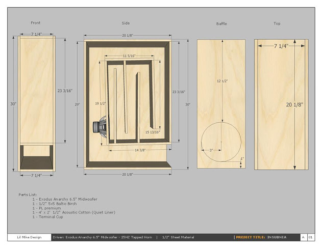

Here are the plans posted by radman12 here : Reed Exodus Anarchy 25hz Tapped Horn - AVS Forum | Home Theater Discussions And Reviews
Note that my sims are based on a deeper box. So the side view is EXACTLY the same as the Insubnia, but the depth is enlarged to fit the 8" woofer. I used an internal depth of 8.5." You could increase it to 9" with little to no change, if your woofer requires the additional depth.
The cut plans posted by radman12 won't work, due to the additional depth, so you'll have to make your own.
Note that the response really doesn't vary much between the Alpine and the Fosgate.
Here's the TS parameters of his woofer.
Here is the frequency response and excursion of that user's woofers in the recommended sealed box, and in the tapped horn described in this thread. We see a really nice bump at 30hz - twenty decibels. That's like going from a one hundred watt amp to a ten thousand watt amp! Of course the tapped horn is way bigger than the recommended box, but you can't escape Hoffman's Iron Law.
The really narrow bandwidth of the sealed box is due to the very high inductance of the user's woofers. Those woofers from the nineties didn't have shorting rings, and the relatively high power handling comes with a penalty of high inductance.
Note that the design is simulated with 250 watts into 2 ohms (22.36V.) In a sealed box, it can take this, but in a tapped horn, it will exceed it's excursion limits. You probably don't want to use more than 200 watts with the TH.
Here are the plans posted by radman12 here : Reed Exodus Anarchy 25hz Tapped Horn - AVS Forum | Home Theater Discussions And Reviews
Note that my sims are based on a deeper box. So the side view is EXACTLY the same as the Insubnia, but the depth is enlarged to fit the 8" woofer. I used an internal depth of 8.5." You could increase it to 9" with little to no change, if your woofer requires the additional depth.
The cut plans posted by radman12 won't work, due to the additional depth, so you'll have to make your own.
Note that the response really doesn't vary much between the Alpine and the Fosgate.
Last edited:
That's correct. The suggest box from Fosgate rolls off quickly. When you add in cabin gain, the sealed box will probably be almost flat to 20hz. (In a car, you get about 12dB gain at 40hz and 24dB gain at 20hz.)
So the Fosgate sealed box will be close to flat, once cabin gain is factored in. I generally find that sounds "lean" in a car though. Due to the roar of road noise, I like a rising response at low frequency in a car. And due to that, the TH will work nicely.
Ideally I'd probably prefer a 6dB rise, not a 12dB rise, but you can fix that with EQ.
I could adapt jbell's idea in post #2 of this thread... http://www.diyaudio.com/forums/subwoofers/167461-mcm-8-dual-tapped-horn-plan.html
I have exactly 40" between my wheel wells in my bed, (the extra 1/4" will not be an issue), and could fire the mouth right into the cab via a relocated blow through.
The truck has a very small cab and cabin gain kicks in around 65-70 Hz and would prefer a rising response to at least 30Hz. Would this get me in the ball park?
Man I want to play with Hornresp so bad it's starting to hurt.
Last edited:
Ok, I got my grubby hands on HornResp and have run this model (post #44) myself.
I am worried about the phase I am seeing. At 40 Hz phase shifts from 180 to -180. That's a 360 degree phase shift! Right? This cannot be a good thing.... Right? Lol
Oddly enough the phase shift is about 117 degrees with two drivers in the same cabinet but response dips a little lower around 60 Hz.
This is fun, but intimidating at first.")
I am worried about the phase I am seeing. At 40 Hz phase shifts from 180 to -180. That's a 360 degree phase shift! Right? This cannot be a good thing.... Right? Lol
Oddly enough the phase shift is about 117 degrees with two drivers in the same cabinet but response dips a little lower around 60 Hz.
This is fun, but intimidating at first.
Not good, not bad, just a display feature. When the phase response reaches +180, another degree of phase change causes the screen to "wrap", one additional degree (not 360) shows as -180.I am worried about the phase I am seeing. At 40 Hz phase shifts from 180 to -180. That's a 360 degree phase shift! Right? This cannot be a good thing.... Right? Lol
Using the Offset delay correction used on the Phase response screen, differing delays will result in a different phase curve, no delay shows "Standard Wrapped Phase".
Have fun!
Not good, not bad, just a display feature. When the phase response reaches +180, another degree of phase change causes the screen to "wrap", one additional degree (not 360) shows as -180.
Using the Offset delay correction used on the Phase response screen, differing delays will result in a different phase curve, no delay shows "Standard Wrapped Phase".
Have fun!
Awesome! Thank you for the information.
I am trying to figure out how to simulate relocating the mouth of the Insubnia in HR.
Below I have an awsome MS paint diagram showing the relocated mouth in red.
this would allow me to set two 8" versions of the Insubnia side by side in my bed with the mouths coupled in the center.
Im just trying to figure out what exactly I need to change on the input screen. I suspect not alot.
Thanks for any help y'all, Im learning and having alot of fun.
Below I have an awsome MS paint diagram showing the relocated mouth in red.

this would allow me to set two 8" versions of the Insubnia side by side in my bed with the mouths coupled in the center.
Im just trying to figure out what exactly I need to change on the input screen. I suspect not alot.
Thanks for any help y'all, Im learning and having alot of fun.
Last edited:
The last "L" is the distance from the driver to the horn mouth, the red opening would be reduced compared to the original.I am trying to figure out how to simulate relocating the mouth of the Insubnia in HR.
Below I have an awsome MS paint diagram showing the relocated mouth in red.
this would allow me to set two 8" versions of the Insubnia side by side in my bed with the mouths coupled in the center.
Im just trying to figure out what exactly I need to change on the input screen. I suspect not alot.
Suggestion: you may have a better sleeping experience putting the subs under rather than in your bed, but whatever turns your crank
The last "L" is the distance from the driver to the horn mouth, the red opening would be reduced compared to the original.
Suggestion: you may have a better sleeping experience putting the subs under rather than in your bed, but whatever turns your crank
Oh,.... LMFAO!! I bet I seem like some kinda of freak.
This is for the bed of my pickup truck. The mouths will fire into the cab though a blow through.
Oh, I get it, a glory holeThe mouths will fire into the cab though a blow through.
...Oh, I get it, a glory hole
Yeah! You know, for the "Wanging" bass......
um,.............. yeah!
The last "L" is the distance from the driver to the horn mouth, the red opening would be reduced compared to the original.
Suggestion: you may have a better sleeping experience putting the subs under rather than in your bed, but whatever turns your crank
So,.... If my understanding is correct I can build that last L straight, (unfold the last bend),and if S3, S4 and L34 stay the same the simulation remains unchanged.
Please excuse the crude drawing. The drawing is close to scale but not accurate.
It serves it's purpose right now.
If I unfolded the last bend and kept S3 and S4 the same and adjust L34 for lack of the 90 degree bend would the enclosure sound the same.
I have played around in HR and discovered that reducing S4 and shortening L34 don't really change the FR that much.

Im working on it in sketch up but its going to be a little bit before it's ready. Lol
If my guesstimations are correct I should just hit 130 dB @ 30-80 Hz with a pair of these on 400w @ 2 ohms once loaded in the truck.
Last edited:
Please excuse the crude drawing. The drawing is close to scale but not accurate.
It serves it's purpose right now.
If I unfolded the last bend and kept S3 and S4 the same and adjust L34 for lack of the 90 degree bend would the enclosure sound the same.
I have played around in HR and discovered that reducing S4 and shortening L34 don't really change the FR that much.
Im working on it in sketch up but its going to be a little bit before it's ready. Lol
If my guesstimations are correct I should just hit 130 dB @ 30-80 Hz with a pair of these on 400w @ 2 ohms once loaded in the truck.
I had already bought plans for an Autotuba and even started building it. I'm changing directions, no way the AT would play this low and loud.
- Status
- This old topic is closed. If you want to reopen this topic, contact a moderator using the "Report Post" button.
- Home
- Loudspeakers
- Subwoofers
- Tapped Horn for the Lazy and Impatient