TH18 Reference Build Complete
Hey All,
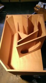
I fashioned myself a nice tapped horn and got to play meet the neighbors the other day:
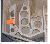
- TH18 Reference Design
- CNC Cut
- B&C 18SW118
- QSC PL340
- Ashley Protea 3.6 DSP
For those of you who've yet to build one of these things let me say- this design produces non-trivial amounts of bass. After a quick high pass config on the DSP I started ramping up the volume. The first impression was that it takes a lot of power to get it started. But then it takes more power- and more power and gets louder and louder. In moments debris began falling off the ceiling then the shelves came loose dumping items all over the floor. I cut the volume off and my neighbor came walking around the corner wide eyed grabbing her chest and acting like she was under attack. By the end of the test session I had met more neighbors and had two friends standing on the inner front of the mount with the cabinet tilted up leaning on it so we could hold it still while running at full volume. Success!
Observations:
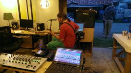
- I've played out doing live improve house twice; the cabinet musically sounds very smooth
- Wide eyes and chest grabbing are common responses I see from audience members
- Hand placing the parts with glue only lead to 1-2mm drift at the outer corners of the cabinet
- The casters vibrate and will need to be replaced
- Neutrik Speakon connectors will not mate unless you're mindful during parts selection
- I wired the QSC PL 340 in bridge mode but left the selector in parallel mode and blew a rectifier in the HF switching stage and lifted a few traces off the main board... Ooops...")
- The B&C 18SW118 driver has insane power handling capacity
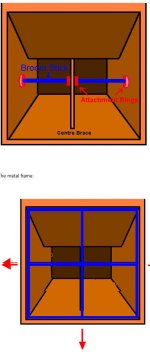
- Needs MORE BRACING
Thanks all for the great info on this thread! More builds to come ...
-lc
Hey All,
I fashioned myself a nice tapped horn and got to play meet the neighbors the other day:
- TH18 Reference Design
- CNC Cut
- B&C 18SW118
- QSC PL340
- Ashley Protea 3.6 DSP
For those of you who've yet to build one of these things let me say- this design produces non-trivial amounts of bass. After a quick high pass config on the DSP I started ramping up the volume. The first impression was that it takes a lot of power to get it started. But then it takes more power- and more power and gets louder and louder. In moments debris began falling off the ceiling then the shelves came loose dumping items all over the floor. I cut the volume off and my neighbor came walking around the corner wide eyed grabbing her chest and acting like she was under attack. By the end of the test session I had met more neighbors and had two friends standing on the inner front of the mount with the cabinet tilted up leaning on it so we could hold it still while running at full volume. Success!
Observations:
- I've played out doing live improve house twice; the cabinet musically sounds very smooth
- Wide eyes and chest grabbing are common responses I see from audience members
- Hand placing the parts with glue only lead to 1-2mm drift at the outer corners of the cabinet
- The casters vibrate and will need to be replaced
- Neutrik Speakon connectors will not mate unless you're mindful during parts selection
- I wired the QSC PL 340 in bridge mode but left the selector in parallel mode and blew a rectifier in the HF switching stage and lifted a few traces off the main board... Ooops...
- The B&C 18SW118 driver has insane power handling capacity
- Needs MORE BRACING
Thanks all for the great info on this thread! More builds to come ...
-lc
Attachments
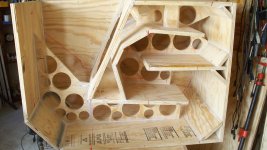
Well as I see it in your pic, there is no bracing on any internal panels.....
does bracing affect spl and perfomance?
A bungee cord wrapped around them will stop the noise.- The casters vibrate and will need to be replaced.

Hi Johan, that makes sense but only at low frequencies. Is that not what happens when the driver becomes unloaded below the resonant frequency and a hi-pass filter is needed to avoid excessive excursion.
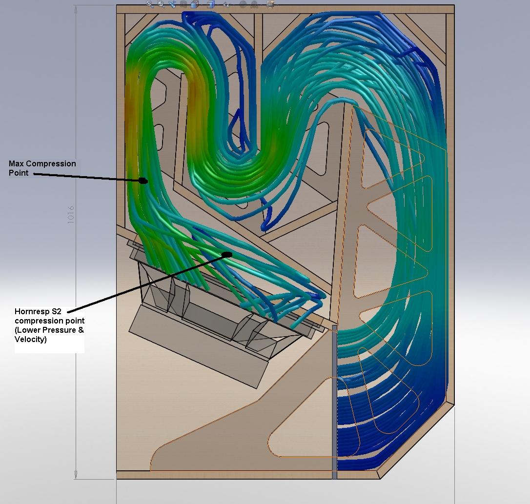
I think that the maximum compression in the TH horn is reached at the point in the horn next to the edge of the driver, not the centre.
As such the Hornresp compression ratio reported is still useful information but does not specifically relate to the actual S2 point in the horn.
Flow analysis sim screenshot attached to illustrate this.
I am trying to concider what is really happening in the TH horn throat.
Regards Martin
Xoc1,
What software are you using to model the 3d flow inside the speaker cabinet? Nice work! My question is since the flow is oscillatory, you have an asymmetry of the flow patterns in the forward vs reverse direction due to corners and edges that would cause separation in one direction and not the other. Is this accounted for in your simulation?
Regards,
X
hi Guys,
If you were to use a piece of clear plastic lexon,plexiglass and flood the internal area with smoke would this give a visual on what is happening inside the throat,I remember Danley doing something similar when he was blowing speakers so he could watch them go and fix his problem,I tried to mimic the cone shape in mine and they sound very good but,I had a few of the fine people on this thread helping me along,my hit and miss is good enough ,but I know they could preform better if they were Tweaked a bit,
My 2 cents,
NS
Xoc1,
What software are you using to model the 3d flow inside the speaker cabinet? Nice work! My question is since the flow is oscillatory, you have an asymmetry of the flow patterns in the forward vs reverse direction due to corners and edges that would cause separation in one direction and not the other. Is this accounted for in your simulation?
Regards,
X
QUOTE]
Hi X......
The simulation was done in Solidworks, which in the 3D cad program I use for all my speaker modelling.
The flow program that comes bundled with the software is quite basic. It gives me the option to use Spaghetti like threads or particle like balls for the flow simulation.
The flow analysis screen grab that you re-posted shows the speaker as a flat piston - but it is offset to account for the volume of the speaker cone. This demonstrates the difference in compression along the speaker path with the maximum compression occurring past the S2 point, close to the first speaker fold.
I would not read too much into the results.
Better simulation software is available of course, but the price is a bit steep!
The vibration analysis results I posted at the beginning of this thread were done when I was doing contract work for a local vehicle design company. Not the sort of software that could be justified at home!
Kind Regards
Xoc1
Yes I know! The price is even more than that in the UK.Solidworks standard is ONLY $3995 usd, chump change right hahaha
And there is the £1K yearly subscription fee on top of that to keep up to date!
I use Solidworks in my work and this allows me to also use the software at home.
The benefit is the accuracy with which I can produce a model,adjust the dimensions, and still have confidence that all the components will update accordingly and fit together.
Also as the CAD program is parametric I can use the CAD to drive an unfolded horn sketch. This allows me to instantly see how changing a panel dimension in the horn will effect the unfolded horn shape.
I have no doubt that some of the initial success of the TH18 design was due to the detailed drawings that I posted. You can cut the panels as detailed and they fit!
https://www.youtube.com/watch?v=BOwhWyn5ymE
The cost of the software is high, but the benefit is the accuracy of the design process. A competent engineer should be able to model a product, and have reasonable confidence that the physical product should function OK.
This cuts out many of the prototype build stages of product development.
Regards Xoc1
Xoc1,
I have SW standard and it does not have a fluid flow solver. You must have the Pro or Enterprise version. Regardless, the flow solver included is probably very rudimentary (having developed and used comprehensive cfd codes for aircraft in my past life), so you have to take the results with a grain of salt - especially if the flow transitions to turbulent or separates and becomes non laminar. I agree that having a 3d model like SW is invaluable for designing and making sure assemblies for together.
I am not sure if this has already been posted but can I get the unfolded horn profile (CSA as a function of distance) ? I would like to model it in AkAbak. I want to see how different drivers perform.
Thanks,
X
Last edited:
Post 527 in this thread has a Akabak Sim By TundraLTD to get you started.
http://www.diyaudio.com/forums/subwoofers/190635-th-18-flat-35hz-xoc1s-design-53.html#post2936345
I will try to find the drawing file with all the unfolded dimensions attached.
Regards
Xoc1
http://www.diyaudio.com/forums/subwoofers/190635-th-18-flat-35hz-xoc1s-design-53.html#post2936345
I will try to find the drawing file with all the unfolded dimensions attached.
Regards
Xoc1
Xoc1,
Thanks for pointing me to the post by TundraLTD (nice work there Tundra!). Tundra's model uses 'duct' elements, which I do not believe account for the physical effects of the various folds and turns (which act as inherent fluidic low pass filters). I plan to model the turns as expansions/contractions with a 'waveguide' element where I will include the inertia effect of turns using 'Acoumass', and damping using 'Acouresistance'.
Regards,
X
- Home
- Loudspeakers
- Subwoofers
- TH-18 Flat to 35hz! (Xoc1's design)