and to everyone @ the diy sub department 😀OK. Apparently not enough.
😛Marry Christmas😛

ot ,how are your reconed speakers holding up,and what did you do to make them survive.?
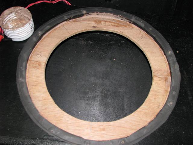
epa; The pyro box speakers are holding up well. I raised the low cutoff to 40hz for now and set the brick wall limiters. Over the winter I will be restricting the throats and cheaking the excursion to see how hard I can push them.
One of the last shows I did with them I had all 8 up on 7 foot scafolding at a race track along side the pits on 9-11. The people could not go in their trailers because the subs were rocking them so hard. It was like the pyro boxs turned them all into drums. LOL
One of the last shows I did with them I had all 8 up on 7 foot scafolding at a race track along side the pits on 9-11. The people could not go in their trailers because the subs were rocking them so hard. It was like the pyro boxs turned them all into drums. LOL
Hey PASC,
Could you post the images instead of linking back to your host page? They have adds for adult stuff above your images. Use the link for your picture and the tag.[/QUOTE]
Learned.
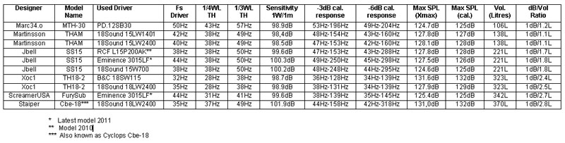
Round restriction, as indicated by jbell, at the throat to reduce travel of the cone and so thermal compression at the limits.
[url]http://img1.uploadhouse.com/fileuploads/15296/1529618099c2bb73abec30e6b8a3d7caa3d91033.jpg[/url]
Trying the B&C 15CL76 which appears to be a candidate to make SS15 his house;
[url]http://img1.uploadhouse.com/fileuploads/15289/152899916647564c6777743e26d6e9c531809ab5.jpg[/url]
Using it with low-cut at 40Hz till 96/100Hz, by ear it plays bass guitar notes accurately, and with cone control till Pe limit. The bass player liked it, timber, fidelity and loudness are good.
Regards,
Learned.
Round restriction, as indicated by jbell, at the throat to reduce travel of the cone and so thermal compression at the limits.
An externally hosted image should be here but it was not working when we last tested it.
Trying the B&C 15CL76 which appears to be a candidate to make SS15 his house;
An externally hosted image should be here but it was not working when we last tested it.
Using it with low-cut at 40Hz till 96/100Hz, by ear it plays bass guitar notes accurately, and with cone control till Pe limit. The bass player liked it, timber, fidelity and loudness are good.
Regards,
You are getting closer, now all you need are the
Attachments
I think thats a little more than even a furysub..For the record the pyro subs weigh in at 112Lbs.
Now I'm curious.. Ill have to weigh one...lol
Ya, Its a little heaver now. I added 3/8 pressure treated plywood to the bottom to keep the dampness away from the burch ply.I think thats a little more than even a furysub..
Now I'm curious.. Ill have to weigh one...lol
Saltzburg... sorry I'm late but
Furysubs go low enough for dubstep etc with 3015 in them.
I'd almost like to see a ss15 that goes lower but needs more boxes to make up
some db. That would make a pretty modular little system.
Furysubs go low enough for dubstep etc with 3015 in them.
I'd almost like to see a ss15 that goes lower but needs more boxes to make up
some db. That would make a pretty modular little system.
Last edited:
😱😱WOW! Now that's a cool table.. I wish I was so neat and organized🙁
Perhaps adding external dimensions and if they are designed with truck pack friendly wheels
might be usefull. I did have to keep in line with standard truck pack sizes. Two Meyer Up-1 fit perfectly on top of the cab so most don't realize I don't have matching meyer subs. That was another issue I had to deal with.
Thanks, I was having a rough day till I saw the chart..
Ahhh what is a pyrosub? I hunted through the posts already.
Last edited:
4Pyros built his 3015LF SS15 cabinets from 3/4" rather than 1/2" and added some bracing.😱😱WOW! Now that's a cool table.. I wish I was so neat and organized🙁
Perhaps adding external dimensions and if they are designed with truck pack friendly wheels
might be usefull. I did have to keep in line with standard truck pack sizes. Two Meyer Up-1 fit perfectly on top of the cab so most don't realize I don't have matching meyer subs. That was another issue I had to deal with.
Thanks, I was having a rough day till I saw the chart..
Ahhh what is a pyrosub? I hunted through the posts already.
Should be the same as the standard SS15 as far as frequency response and sensitivity.
The chart pretty much reinforces Hoffman's Iron Law.
Thanks for the clarification.. That's what I was planning to do as well for hi hat (pole) mounting. Although I was debating 1/2 inch for the insides and adding about a 1/2 inch width for the bracing.
DJM what about putting the "gold" standard TH-115 or USC-1 on the chart as a reference, or would that be in bad taste?
DJM what about putting the "gold" standard TH-115 or USC-1 on the chart as a reference, or would that be in bad taste?
have a heart scott... I already feel inadequate....
I would love to enter true data for Danley's TH's into my table. But somehow I doubt Tom wants 'us' to reverse engineer his TH's to check his specs on accuracy.
Talking of which, your Furybox definitely needs its own thread for some precise analyses because I'm not sure the data is accurate enough.
Talking of which, your Furybox definitely needs its own thread for some precise analyses because I'm not sure the data is accurate enough.
I would love to enter true data for Danley's TH's into my table. But somehow I doubt Tom wants 'us' to reverse engineer his TH's to check his specs on accuracy.
Talking of which, your Furybox definitely needs its own thread for some precise analyses because I'm not sure the data is accurate enough.
Xoc1’s TH18-2 has the same physical dimensions as the DSL TH-115 or TH-118, and similar frequency response as the TH-118, which uses the BC18SW115-4.
The DSL TH-118 is rated at about 105 dB one watt one meter (spec sheet uses 28.3 volt at 10 meters).
My slightly larger volume Keystone BC18SW115-4 loaded tapped horn actually measures about 98 dB sensitivity in the upper range (same as a JBL-SRX 728, a slightly larger 2x18"), about the same as Xoc1’s TH18-2 Hornresp sims.
I have communicated about the disparity with Tom Danley, although he agreed that the disparity sounds too large, he stands by the spec sheet figures. He did share the actual plans of the TH-115 with me, Xoc1’s TH18-2 are nearly identical other than one small detail that Tom does not believe would make much difference in sensitivity.
Josh Ricci has tested a DSL DTS-10, his test results show a much lesser sensitivity than Danley’s spec sheet, very much in line with the disparity between Xoc1’s TH18-2 or my Keystone compared to the DSL TH-118.
My tests showed the TH increased the sensitivity of the BC18SW115-4 by 6 dB over a slightly smaller BR cabinet with the same low corner.
Six dB is a big deal, another 6 or 7dB on top of that with the same FR and cabinet volume (and fold pattern) is IMHO, impossible.
Art Welter
The 18SW115-4Ohm version also does peak 105dB in the Xoc1-TH18-2 with 2,83V but that is peak (95Hz) and not average and with 2,4W/1m.
Last edited:
Starts with post #584 of this thread. It is not a true SS15 it takes about a sheet and a half.Ahhh what is a pyrosub? I hunted through the posts already.
I'd like to revisit the fury through building another one but time has not been my friend for a few years now. I was under the gun at the time and expected you guys to surpass it.
The CTH-15 was the best sounding and loudest box I came up with but there were so many small parts that it was not practical to build. That one was hitting 103-104 so Danleys spec may be quite right.
We learned a lot building these, with quite satisfying results, within our meager budgets.
On the ss15.. JBell seems to have optimized it pretty darn good. The only thing I notice is there may be a cheezy useful mod for it.
If you decrease s5 you get more low end extension at the cost of a few db...so:
Hows about a removable wedgie? 😀 Heavy duty velcro on the bottom and felt or carpet on the sides for a snug fit. You could add another box and toss the wedgies in to drop the low end 5hz or more. The added impact to the audiences central nervous system should do the trick without having to push the system any harder.. Thoughts? 😉
The CTH-15 was the best sounding and loudest box I came up with but there were so many small parts that it was not practical to build. That one was hitting 103-104 so Danleys spec may be quite right.
We learned a lot building these, with quite satisfying results, within our meager budgets.
On the ss15.. JBell seems to have optimized it pretty darn good. The only thing I notice is there may be a cheezy useful mod for it.
If you decrease s5 you get more low end extension at the cost of a few db...so:
Hows about a removable wedgie? 😀 Heavy duty velcro on the bottom and felt or carpet on the sides for a snug fit. You could add another box and toss the wedgies in to drop the low end 5hz or more. The added impact to the audiences central nervous system should do the trick without having to push the system any harder..
Thoughts? 😉It looks like a couple of different size wedgies would give you options. Dance music use a smaller one for more ummph, Theater/corporate presentation use a bigger one for more rumble. You could even have hand holes to carry them and pull them out with right on the front. Or leave a compromise size glued in. Same cabinet, different options for different events.
- Home
- Loudspeakers
- Subwoofers
- Single sheet TH challenge