Post #691.
Hi Djim,
I think you're looking for a victim to draw your suggestion from Post #691, i'll see if I can fit it in in the next few days. 🙂
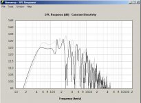
You may want to take a look at how your design compares to the SS15 @ Xmax (9.6mm) in the pass band (the SS15 is shown with a reduced S1 too).
Regards,
Hi Djim,
I think you're looking for a victim to draw your suggestion from Post #691, i'll see if I can fit it in in the next few days. 🙂
You may want to take a look at how your design compares to the SS15 @ Xmax (9.6mm) in the pass band (the SS15 is shown with a reduced S1 too).
Regards,
Attachments
Last edited:
Correct, a front loaded top cabinet would need to be delayed by the TH path length, plus any filter time delay contribution, to properly time align.surely it's the faster responding (closer) drivers that need to be delayed??
It looks like my Keystone TH, a longer path length than the SS15, would require front loaded top cabinets to be delayed by 10.5 ms for proper time alignment.
Fortunately, my top cabinets are short horns a bit over 1 ms deep, so the DSP I use, which only has 9 ms delay capability, should be just barely adequate.
Setting crossovers seemed so much simpler before learning more about phase, polarity, filter latency, arrival time and what each does in the big picture...
Art
art:
a few construction details on your keystone th? is it functioning more like a bandpass, than tapped?
a few construction details on your keystone th? is it functioning more like a bandpass, than tapped?
Oliver, I hope the victim feels less victimised when I say: I would be more than pleased and take your time ;-)Hi Djim,
I think you're looking for a victim to draw your suggestion from Post #691, i'll see if I can fit it in in the next few days. 🙂
You may want to take a look at how your design compares to the SS15 @ Xmax (9.6mm) in the pass band (the SS15 is shown with a reduced S1 too).
Regards,
I know the Xmax will gets extended when the Fs of the system drops. But in this case 60Volts (450watt) is reaching the 12mm theoretical excursion. 12mm is still under [(Xmax + Xlim) : 2] so I’m not worried and it is equal to its continues power rating.
What I’m more worried about is the total path-length. I need that 280cm to hit 40Hz at 1/3 wavelength and to make sure the low-cut filter can be set at 32/33Hz. This will make a big difference in the 40Hz area.
If you need extra lengths you can extend S1 a little more.
The Keystone functions like any TH, though the fold pattern allows for changing mouth size and shape easily, which affects the frequency response.art:
a few construction details on your keystone th? is it functioning more like a bandpass, than tapped?
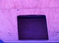
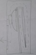
The fold pattern also allows the exit to be on the front (as built, and shown in the diagram below) or the side or bottom, though a bottom exit would not benefit from the keystone shape.
My achievement is that I am perhaps the first to realize that the Keystone exit shape is needed for this type of fold to act more like a TH similar to the DSL TH-115 or 118, the Apache, or the SS15, all of which have a more "normal" horn exit.
If there is anyone that has used the keystone shaped exit on a TH before me, I am unaware of it. I thought of it by visualizing what shape would be needed to act like a square exit when looking down a long duct. The left picture below shows the Keystone exit from a high overhead angle.
The response curve of the Keystone is almost exactly the same in magnitude and phase as a DSL TH-118, which uses the same driver. My tests show the Keystone to be about the same sensitivity as the dual 18" JBL SRX 728, while Danley's charts show the TH-118 as almost 7.5 dB higher in sensitivity. Hmmm..
Closing the upper portion of the Keystone mouth makes the path length longer, exit delay increases accordingly.
Reducing the mouth size by covering a portion of it on the SS15 ("step down" mode) would make the low corner lower, but won't increase the path length, so efficiency would take a bigger hit than it does on the Keystone.
I agree with your assessment that the SS15 is optimized for what it can do. I think the posts showing longer path lengths and a lower corner are too optimistic in the amount of LF output level that could be achieved, trying to squeeze more LF out of a TH that size will waste the upper bass response.
Once the upper bass advantage is gone, one might as well use a BR, a pair of 4015LF in a box the size of the SS15 would put out more LF than an "extended path" SS15, which probably could no longer be made from a single sheet anyway.
Attachments
Last edited:
Any energy delivered to the driver will initially come from the back of the speaker (the part nearest the mouth), as sound. Any sound comming thru
the "horn" will arrive later.
Your "keystone" arguement is even less convincing. There is no advantage when the mouth is larger than the end of the flare. You can "look" at it
any way you want, but that's light ... not air, and we don't listen to light.
the "horn" will arrive later.
Your "keystone" arguement is even less convincing. There is no advantage when the mouth is larger than the end of the flare. You can "look" at it
any way you want, but that's light ... not air, and we don't listen to light.
Last edited:
Art, I agree with all your criticism... As well with your statements in favour of my extension idea 🙂
Ok... since there has been much talk spent on 28v vs 2.83v measurements.... And I'm a fan of 'There is no substitute for doing...' I went and did something a bit crazy today. The crown was set for 40-300hz. (and yes, even a butterworth 48db/oct at 40hz cuts a couple db at the high pass freq.) The pictures speak for themselves.
Not sure what the pictures are saying, other than the 3 dB down point with the 40Hz filter is now about 55 Hz, and the 10dB down point 40 Hz.
As you said August 2008:
JBell quote: “If 40hz is your low frequency that you need for your PA, that efficiency at that freq sets the overall response you can achieve, as it's the hardest to reproduce and most power intensive frequency in the PA power band. (which we obviously know) A sub that's 13db more efficient at 100hz vs 40hz, helps little. If I need more 100hz out of a sub, I'll eq it in. However, If I need more 40hz... there's only one way to get that, big power and big excursion, and that limits the overall spl you can get out of your cabinet.”
Several years before that I had abandoned my Chorn design for Lab 12” in ported cabinets, like you I was willing to sacrifice the upper response for a gain in the lower response. The Chorn behaves like BFM’s and Jeff Permian's offerings.
Closing the upper portion of the Keystone mouth makes the path length longer. Reducing the mouth size by covering a portion of it on the SS15 ("step down" mode) would make the low corner lower, but won't increase the path length, so efficiency would take a bigger hit than it does on the Keystone.
Once the upper bass advantage is gone, one might as well use a BR, a pair of 4015LF in a box the size of the SS15 would put out more LF than an "extended path" SS15, which probably could no longer be made from a single sheet anyway.
In listening tests with both cabinets equalized to have the same frequency response and output, the primary difference was the port noise in the BR when pushed to the amp’s limit.
When the TH was pushed to the amp’s limit, it was basically noise-free, and 6 dB louder than the BR.
Last edited:
You probably mean that any energy delivered at the listening position or test microphone from the back of the speaker will arrive first, and the horn output will come later, which I agree with.Any energy delivered to the driver will initially come from the back of the speaker (the part nearest the mouth), as sound. Any sound comming thru
the "horn" will arrive later.
.
The TH is an interesting arrangement where the front and back outputs combine "in phase" over a fairly wide bandwidth compared to a BR cabinet.
This allows around a 6 dB advantage in the case of the THs I have built and tested over a BR cabinet using the same speakers.
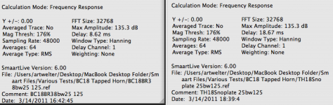
The "horn" output of a TH is doing the heavy lifting. The Smaart delay finder responds to HF, if the upper output of the TH was loud enough to register, the delay finder would deem the TH the same delay as a BR.
The TH output is delayed by the horn path length, as is clearly shown below.
Anyone using the dual FFT function of Smaart or similar systems can easily verify this fact.
If one wants to get a system to sound best at the crossover point, knowing the propagation delay of the low and high speakers is an important data point.
Perhaps Jbel will verify the path length of the SS15, with Auto Sm using his Smaart system.This would show the actual SS15 acoustic path length, which is not always the same as what a squiggly line through the middle of all the folds is.
Attachments
is it possible to mix box types. example, could u make a bandpass design with a TH/tline in one chamber and a ported design in the other.?
after reading about TH and how you can achieve a chord like effect from many freqencies layered.iam curoius what u can do. iam a sound engineer/music producer so have a good idea of what frequencies to layer.
phase shift ????????
when i make sub basses using synths hardware or software ,i often find the best way to get it from a sine wave to fat sub , is using a small amount of pitch adjustmentm using decay controls on an envelope.
also the key thing i find is the start phase/position of the wave. if u take 2 sine waves and shift the phase/position off one u can make the sound louder/fatter , it can also cause phase and canceling out of the sound at wrong positions.
how would u control the phase/position of the wave to create a fatter sounding box?.
could a band pass design have the 2 chambers then go in to one chamber combining the waves.
do i make any sense ? :}
Last edited:
Sorry Djim, I am not in favor of your extension idea, I think the response extension you post is overly optimistic considering what the real SS15 LF corner is already.Art, I agree with all your criticism... As well with your statements in favour of my extension idea 🙂
I still agree with Jbel that the SS15 is pretty optimal for size/weight/cost/output. Reducing the LF corner will probably push the efficiency down to where there would be little advantage over a bass reflex cabinet.
That said, no one will know for sure unless they try cramming more path length in the same box size and test the results side by side.
SS15 Analysis
For what its worth I have done another unfolded drawing analysis of the SS15
as Djim requested. 🙂
The dimensions are as accurate as I can acheive given the available drawings.
The central 8" divider is reduced to 7 3/4" as Jbell commented.
No attempt at suggesting how to emulate this in hornresp. or any adjustment for the driver volume. This is as close as I can get to Jbells as built box.
The internal volume of the box is 223 Litres
The equivalent unfolded horn is 225 Litres. This represents an error of less than 1%😀
The PDF should be printed as as 100% on A4 for 1:10 scale.
Can the SS15 be improved?- Probably, but you might need to relax the single sheet rule to acheive it😉
Attachments
is it possible to mix box types. example, could u make a bandpass design with a TH/tline in one chamber and a ported design in the other.?
how would u control the phase/position of the wave to create a fatter sounding box?.
I suppose "u" could make a bandpass design with a TH/tline in one chamber and a ported design in the other. I have no idea what it would sound like, or why "u" would want to.
Phase response of any box is dependent on a large number of variables. The last thing I want is a "fatter sounding" box, I want a box with as flat frequency and phase response possible over the widest range.
The phase response of a properly designed horn or TH will be smoother over a wider range than a BR (AKA phase inversion) box.
I suggest you start another thread with your questions about other box types and hybrids, they really have nothing to do with the SS15.
Thanks Martin and of course this will help! And your PDF integrates perfectly within the 1:10 ratio in PhotoshopFor what its worth I have done another unfolded drawing analysis of the SS15 as Djim requested. 🙂
The dimensions are as accurate as I can acheive given the available drawings. The central 8" divider is reduced to 7 3/4" as Jbell commented.
No attempt at suggesting how to emulate this in hornresp. or any adjustment for the driver volume. This is as close as I can get to Jbells as built box.
The internal volume of the box is 223 Litres
The equivalent unfolded horn is 225 Litres. This represents an error of less than 1%😀
The PDF should be printed as as 100% on A4 for 1:10 scale.
Can the SS15 be improved?- Probably, but you might need to relax the single sheet rule to acheive it😉

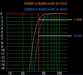
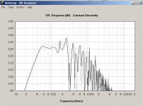
Here is a graphic representation of 2 Butterworth 48dB per Octave - lowcut filters. One is set to 40Hz (for standard SS15) and the other at 33Hz (Extended SS15).
As you can see the difference between the filters at:
35Hz = 7dB
40Hz = 4,5dB
45Hz = 1,9dB
50Hz = 0,9dB
So even IF the extended version is not more efficient at 40Hz there still will be a difference of +4,5dB in favour of the Extended at 40Hz and +7dB in favour of the Extended at 35Hz.
I believe my prediction of +5dB at least and probably +7dB at 40Hz is not that unrealistic, and who was blaming who about exaggerating?😉
Attachments
Last edited:
hmmm.... my smaart was done with a 40hz@48 - 250hz@24.... Makes me think I should redo that measurement with a 35hzHP....
I was hoping you were reading this 🙂 but don't use any type of filtering with 1V/1M measurements.
Now you understand my motivation for Pe -10dB measurements instead of a steady number like 28,3V/10m. At Pe -10dB all PA drivers are safe and you don't need to worry about excursion to much. Also it shows the performance of each driver at the exact same point so high power drivers have not an advantage...
Now you understand my motivation for Pe -10dB measurements instead of a steady number like 28,3V/10m. At Pe -10dB all PA drivers are safe and you don't need to worry about excursion to much. Also it shows the performance of each driver at the exact same point so high power drivers have not an advantage...
If there is anyone that has used the keystone shaped exit on a TH before me, I am unaware of it.
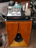
Karlson K15... Definately tapped and "keystoned?", but horn???
Karlson himself often claimed it was mathematically equivalent.
And Klipsh would flip his BS tie every time that was said...
Using multiple stagger tuned resonant chambers rather than a
much longer and voluminous expanding path, its never been
modeled correctly that I know of. I could not explain exactly
why it works, but definitely does not suck in the 1 sheet dept.
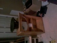
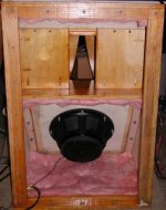
Yeah, that undersized thing is only a DeltaPro12 in the picture.
There's a SigmaPro18-A2 in there now, just barely fit... 18 goes
much much lower, but the 12 really "hit" insanely hard.
No special reason couldn't have been mounted magnet forward
if only gonna serve as a sub and not full range. OK, that might
not be as simple as I just claimed, the baffles a little too close
to the front exit if built to the original plan.
Attachments
Last edited:
Post #691 - Continued
Hi Y'all,
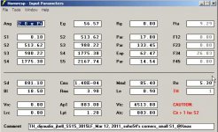
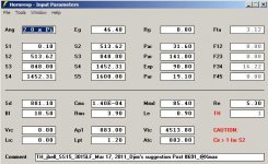
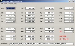
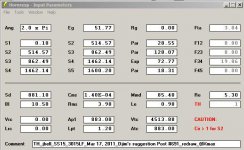
Another page in the story of the SS15, sadly it's still not getting better. I believe using Xmax in the passband as a comparison is valid. Anyway, again Hornresp inputs, and combined SPL. Additionally I'll post a .pdf with the original, and the redrawn versions of Djim's Post #691 (and don't even ask, I'm not going to do a layout of the original this was already way to much time spend on this idea 🙂, should anyone have a need for the original Acad 14 .dwg just PM me).
Y'all have been busy, and Xoc1 has outdone himself in the drawing department.
Regards,
Hi Y'all,
Another page in the story of the SS15, sadly it's still not getting better. I believe using Xmax in the passband as a comparison is valid. Anyway, again Hornresp inputs, and combined SPL. Additionally I'll post a .pdf with the original, and the redrawn versions of Djim's Post #691 (and don't even ask, I'm not going to do a layout of the original this was already way to much time spend on this idea 🙂, should anyone have a need for the original Acad 14 .dwg just PM me).
Y'all have been busy, and Xoc1 has outdone himself in the drawing department.
Regards,
Attachments
Last edited:
Hi Y'all,
Another page in the story of the SS15, sadly it's still not getting better. I believe using Xmax in the passband as a comparison is valid. Anyway, again Hornresp inputs, and combined SPL. Additionally I'll post a .pdf with the original, and the redrawn versions of Djim's Post #691 (and don't even ask, I'm not going to do a layout of the original this was already way to much time spend on this idea 🙂, should anyone have a need for the original Acad 14 .dwg just PM me). Y'all have been busy, and Xoc1 has outdone himself in the drawing department.
Regards,
Oliver I have to admit you have done another tremendous job, and many thanks for that.... The drop in SPL is no problem but dear oh dear...that path length (this frase is followed by a big sigh, a verrrry deep big sigh). I desperately needed that 280cm (110inches) in path length, this is 'just' 45Hz instead of the original 47Hz! By bringing S1 up to the top I can gain what... 10cm (4inches)... that brings me to 44Hz, still not enough....Aaahhhrrrggg &#$*&@!
Oliver, could you please check the path length cause when I put the new path length on top of the original SS15 path, I see considerably more length then just the extra 10cm. Or what am I doing wrong here? (I have perfectly scaled each drawing so the outlines of the cab are exactly the same).
Last edited:
- Home
- Loudspeakers
- Subwoofers
- Single sheet TH challenge