Note that the path length difference relates to acoustic path lengths external to the speaker system, not to acoustic path lengths internal to the speaker system.
Hi David,
How does one deal with ports internal to the system, like when the port is in the throat of an OD horn?
1. Square will be close to round of the same area, but rectangular will not be so close, and further off as frequency increases.
2. There are too many variables in cone breakup, suspension oddities, narrowing beamwidth etc. to assume anything above the high end roll-off.
If you are afraid to waste some wood, a scissors, cardboard and some duct tape will give you a very good idea of what your horn design will sound like, long as you don't turn it up too loud.
One can often find a kitchen pot that will work for a compression chamber too, but the cook may not approve it's use, and duct tape residue can be tough to remove..
Thanks Weltersys. Not concerned with wasting wood. A friend of mine owns a saw mill and I can get as much pine and oak as I need.
OK, when I get the graph and it shows high and low rolloff, should I be crossing over to a mid at the point of the high rolloff, or is it just a test and see type deal?
How does one deal with ports internal to the system, like when the port is in the throat of an OD horn?
You let Hornresp deal with that
") All lengths of chambers and ducts are included in the Hornresp calculations. All you have to worry about, is the length differences between the listener and the parts that radiate into the air, like the horn mouth, port opening etc.
All lengths of chambers and ducts are included in the Hornresp calculations. All you have to worry about, is the length differences between the listener and the parts that radiate into the air, like the horn mouth, port opening etc. Bjørn
Hi Bjørn,You let Hornresp deal with that
Bjørn
Are you telling me is there no need to specify where the port is along the internal path of the horn? That seems quite counter intuitive considering the effect of driver position in a TH.
I was into the "zero" at first but I got, as you say, confused after reading the help and instructions before my previous post.
Hi Lars,
Thanks for raising this issue. I can see now how the notes under the Combined Response section in the Hornresp Help file could be somewhat confusing / ambiguous. When I say that "the rear path length can be adjusted if necessary using the path length difference parameter", I do not make it clear that the rear path length I am referring to is the distance from the port outlet to the listener. I will rectify this in the next release.
Kind regards,
David
Hi Bjørn, Are you telling me is there no need to specify where the port is along the internal path of the horn? That seems quite counter intuitive considering the effect of driver position in a TH.
Hi Dan,
I don't think that is what Bjørn is saying at all
.The Hornresp path length difference parameter value takes into account any difference in the distances from two radiating sources to the point at which the combined signals are measured / observed. This is necessary to ensure that the relationship between the phases of the two signals being combined, remains correct.
The port in your example is an acoustic duct internal to the loudspeaker system, it is not a radiating source. The location and dimensions of the port are known by the program because they have been specified as input parameters.
Kind regards,
David
I don't think that is what Bjørn is saying at all
Correct
I thought you asked about how the path length difference parameter related to the position of an internal port, and wanted to point out that they are unrelated. The position of the internal port is already specified in the input parameters, as David points out.Bjørn
Thanks David,Hi Dan,
I don't think that is what Bjørn is saying at all
The Hornresp path length difference parameter value takes into account any difference in the distances from two radiating sources to the point at which the combined signals are measured / observed. This is necessary to ensure that the relationship between the phases of the two signals being combined, remains correct.
The port in your example is an acoustic duct internal to the loudspeaker system, it is not a radiating source. The location and dimensions of the port are known by the program because they have been specified as input parameters.
Kind regards,
David
I think I understand both points. I've re-read the notes and I'm still unsure the relationship between the rear of the driver cone and the internal end of the port can be effectively translated into the real entrypoint along the pathlength of the horn.
Hi Bjørn,Correct
Bjørn
I was probing for a good explanation on how to enter the location of the port.
***
Here is a link to an Evernote of the Hornresp notes, they are searchable
You will need the free Evernote application/account to view -highly recommended.
As I read you here, and from the following posts...How does one deal with ports internal to the system, like when the port is in the throat of an OD horn?
If a rear chamber port is tapped into the forward horn somewhere, instead of exiting from it's own external enclosure orifice, it is no longer an OD horn with a vented rear chamber, it is a TH.
Unfortunately, it is a form of TH Hornresp doesn't do natively, so it's a horn for AkAbak.
You can use HR (in a pinch) to sim it as an OD with the combined response option, and just set the rear port tap position to the listener as it physically is. As you are thinking though, it will not be exact, and depending on several variables, it can be very wrong. The port in the throat would count as a "very wrong" variable.
Last edited:
If a rear chamber port is tapped into the forward horn somewhere, instead of exiting from it's own external enclosure orifice
Hi soho54,
Thanks for this - it would seem that I completely misunderstood Dan's original question
.By "when the port is in the throat of an OD horn" I automatically assumed that he was referring to the Ap1 throat chamber port parameter, but I think you are probably right and that he was actually referring to the Ap vented rear chamber port parameter, but with the port output feeding back into the throat of an OD horn. As you have quite rightly pointed out, Hornresp cannot simulate such systems.
Kind regards,
David
Hornresp - Minor Update
Hi Everyone,
The Hornresp Help file has been changed - hopefully the description of the path length difference parameter in the Combined Response section is now a little less confusing. My thanks to Lars for highlighting the ambiguity.
Not that it really matters much, but I have also taken the opportunity to add Cancel buttons to both the Find and the Phase Offset Delay Correction tools.
The new release is Product Number 2830-110313.
Kind regards,
David
I will rectify this in the next release.
Hi Everyone,
The Hornresp Help file has been changed - hopefully the description of the path length difference parameter in the Combined Response section is now a little less confusing. My thanks to Lars for highlighting the ambiguity.
Not that it really matters much, but I have also taken the opportunity to add Cancel buttons to both the Find and the Phase Offset Delay Correction tools
.The new release is Product Number 2830-110313.
Kind regards,
David
Hi David
When exporting data to try and plot a Tractrix horn design what do I select in the following screen?
Note:I havent changed the data on the Export page.
Is it as simple as entering the S1 and S2 from the earlier design? What do I do about the con, exp or uni choice?
Thanks again for your help.
Gregg
When exporting data to try and plot a Tractrix horn design what do I select in the following screen?
Note:I havent changed the data on the Export page.
Is it as simple as entering the S1 and S2 from the earlier design? What do I do about the con, exp or uni choice?
Thanks again for your help.
Gregg
Attachments
Although I have much gratitude to David for Hornresp, no simulation can account for all the variables, so test and listen to the real deal.Thanks Weltersys. Not concerned with wasting wood. A friend of mine owns a saw mill and I can get as much pine and oak as I need.
OK, when I get the graph and it shows high and low rolloff, should I be crossing over to a mid at the point of the high rolloff, or is it just a test and see type deal?
Crossover design is also outside the range of what this thread is about, but simply put, generally you want the crossover point a ways below the high rolloff, as most speakers will not be nice and smooth up there, and peaks in the response can be heard even if they are an octave away using a 24 dB per octave acoustic crossover. With 18, 12, or 6 dB per octave crossovers, smooth response must be extended much further.
Passive crossover design makes cabinet design look like child's play.
Even using digital active crossovers and dual FFT test equipment (and good ears and a good meat processor), good crossover design is very tricky.
And if the crossover design is off, the wonderful cabinets one can design using Hornresp may end up sounding like hammered dog poo.
Is it as simple as entering the S1 and S2 from the earlier design? What do I do about the con, exp or uni choice?
Hi Gregg,
The 'Horn Cross-Section Dimensions' input form allows you to specify the dimensions at each end of a horn segment, assuming that the cross-sectional areas are either rectangular or square at those points.
For the example you have given, S1 = 20.30 and S2 = 6000.00.
By default Hornresp assumes square cross-sectional areas for the exported data, so that:
At S1 the height = 4.51 (square root of 20.30) and the width = 4.50 (20.30 / 4.51)
Similarly, at S2 the height = 77.46 (square root of 6000.00) and the width = 77.46 (6000.00 / 77.46)
The S1 and S2 height values can be changed as required if the cross-sectional areas are not square. The width values will then be altered automatically to maintain the correct cross-sectional areas.
The Con, Exp or Uni 'Width Flare' option specifies how the width increases along the length of the horn segment - this then also influences how the height increases. The Uni option causes the horn segment to flare uniformly in both the width and height directions. This option is most likely the one that you will want to use, I expect.
The radius values for a circular cross-section horn segment are also automatically included in the exported data list.
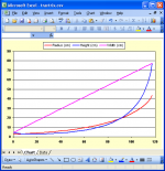
The attached screenprint shows the plotted exported data for your example, using the default square cross-sectional area values and the Con option. The pink trace shows the width expanding "conically", the blue trace shows how the height changes because of the conical width flare, and the red trace shows the radius of an equivalent-area axisymmetric (or circular cross-section) horn segment.
If you choose the Uni flare instead for a square cross-section horn segment, then the pink and blue traces will be the same.
Kind regards,
David
Attachments
Last edited:
I will be building round plywood horns, made of lots of rings of plywood turned up on a diy lathe.
Hi Gregg,
The Height, Width and Width Flare parameters are not applicable to round horns. Simply set the 'Increment' value equal to the thickness of the plywood, and then use the exported length and radius results to construct the horn.
You have specified S1 = 20.30 and S2 = 6000.00 for your 120 hertz tractrix horn, giving a mouth Fta of 73.31 degrees.
Increasing S2 to 6539.49 would give a (fully formed) mouth Fta of 90 degrees.
Also, have you considered the possibility of perhaps using a Le Cléac'h flare, rather than a tractrix flare, for your 120 hertz horn?
Kind regards,
David
"The Con, Exp or Uni 'Width Flare' option specifies how the width increases along the length of the horn segment - this then also influences how the height increases. The Uni option causes the horn segment to flare uniformly in both the width and height directions. This option is most likely the one that you will want to use, I expect."
Ok David, I am getting a feel of this now. I have calculated my Horn for my Chosen Tractrix flare. Can you please expand on the above quote.
I am strill unsure what to choose for my round horns on the con, exp or uni drop down.
I will probably plot the dimensions straight on to a piece of thin MDF which can be used as a turning template.
Thanks again.
- Home
- Loudspeakers
- Subwoofers
- Hornresp