Works perfectly, thanks a lot.1. From the main Input Parameters window select menu commands Help > Input Wizard.
2. From the Input Wizard tool select options Half space > Direct radiator > Band pass > Sixth order series (or Sixth order parallel).
shouldn't the output be at the Port?
Hi rertrobaer,
Yes it should.
Thanks for the feedback - the error will be fixed in the next update.
(The actual simulation results are okay, it's just the System Model diagram that is currently wrong).
Kind regards,
David
What am I doing wrong?
Nothing.
It took me a while to replicate the bug, but I have now done so and will investigate further.
In the meantime, to clear the error simply highlight the S1 input box, press the Backspace key and then press the Enter key.
Thanks for the feedback!
Hornresp Update 5460-230709
Hi Everyone,
CHANGE 1
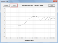
Directivity Index (DI) chart data can now be exported, as shown in Attachment 1.
Inclusion of the new feature was prompted by Bjørn's Post #13,682.
CHANGE 2
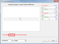
One litre of absorbent filling material was being shown as 1.000 litres in the loudspeaker wizard (see Attachment 2).
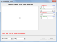
This has now been changed to 1.000 litre as shown in Attachment 3.
BUG FIX 1
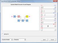
The System Model circuit diagram error identified in Post #13,702 has now been fixed, as shown in Attachment 4.
My thanks to rertrobaer for reporting the bug.
BUG FIX 2
The error identified in Post #13,705 has now been fixed.
My thanks to AllenB for reporting the bug.
Kind regards,
David
Hi Everyone,
CHANGE 1
Directivity Index (DI) chart data can now be exported, as shown in Attachment 1.
Inclusion of the new feature was prompted by Bjørn's Post #13,682.
CHANGE 2
One litre of absorbent filling material was being shown as 1.000 litres in the loudspeaker wizard (see Attachment 2).
This has now been changed to 1.000 litre as shown in Attachment 3.
BUG FIX 1
The System Model circuit diagram error identified in Post #13,702 has now been fixed, as shown in Attachment 4.
My thanks to rertrobaer for reporting the bug.
BUG FIX 2
The error identified in Post #13,705 has now been fixed.
My thanks to AllenB for reporting the bug.
Kind regards,
David
Attachments
Hello papasteack,Hi David,
That is really awesome to tweak port size, it's surprising conter intuitive to see that first segment are lower velocity. Thanks a lot, again !
While you there, there's the (non re-entrant) parrallel 7th, adding a bp to a parrallel 6th order, or venting the 5th order back chamber ^^. Can be actually too simed with PR in Nd/OD actually.
(comment : i use to like smooth response for some reasons, so for some, those are not impressive sims...)
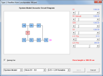
May I ask how were you able to get this type of schematic diagram? If I use Input Wizard to compound horn it wouldn't look like your schematic diagram. I would very much appreciate your help, tks.
Regards,
GQZ
May I ask how were you able to get this type of schematic diagram?
The design can be modelled using stepped segments and either a rear port tube as shown in Attachment 1, or a compound horn as shown in Attachment 2. The results for the two models will be slightly different because the rear port tube includes an internal end correction.
Attachments
Hornresp Update 5460-230719
Hi Everyone,
CHANGE
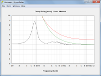
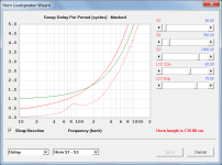
The 1/f and Claus Futtrup limit guidelines can now be added to the main group delay chart where previously they were only available on the Loudspeaker Wizard group delay / group delay per period charts. Also, the limit guidelines have been extended from 4000 Hz to 20000 Hz as shown in Attachment 1.
With the main group delay chart displayed press the L (for limit) key to add the green 1/f limit guideline. Press the L key again to add the red Claus Futtrup limit guideline. Press the L key a third time to remove the 1/f limit guideline and press the L key a fourth time to remove the Claus Futtrup limit guideline.
The Loudspeaker Wizard has been changed to use the same L key functionality as the main chart (rather than double-clicking the wizard delay chart to add the limit guidelines or pressing the Esc key to remove them).
The Help file has been amended accordingly.
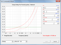
BUG FIX
The green 1/f group delay per period limit guideline was being displayed incorrectly, as shown in Attachment 2. This has now been fixed as shown in Attachment 3.
Kind regards,
David
Hi Everyone,
CHANGE
The 1/f and Claus Futtrup limit guidelines can now be added to the main group delay chart where previously they were only available on the Loudspeaker Wizard group delay / group delay per period charts. Also, the limit guidelines have been extended from 4000 Hz to 20000 Hz as shown in Attachment 1.
With the main group delay chart displayed press the L (for limit) key to add the green 1/f limit guideline. Press the L key again to add the red Claus Futtrup limit guideline. Press the L key a third time to remove the 1/f limit guideline and press the L key a fourth time to remove the Claus Futtrup limit guideline.
The Loudspeaker Wizard has been changed to use the same L key functionality as the main chart (rather than double-clicking the wizard delay chart to add the limit guidelines or pressing the Esc key to remove them).
The Help file has been amended accordingly.
BUG FIX
The green 1/f group delay per period limit guideline was being displayed incorrectly, as shown in Attachment 2. This has now been fixed as shown in Attachment 3.
Kind regards,
David
Attachments
Interesting!
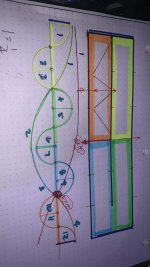
Does horn response use a ‘volumetric ratio’ between the last 1/3 of the long pipe and the entire short pipe, in parallel, to create the ‘out of phase gouge’ in the response?
A few examples here , 2 with the discontinuity in response.
Does horn response use a ‘volumetric ratio’ between the last 1/3 of the long pipe and the entire short pipe, in parallel, to create the ‘out of phase gouge’ in the response?
A few examples here , 2 with the discontinuity in response.
Attachments
-
 3D611509-EB29-4813-ACF6-43CB0E2DC021.png13.7 KB · Views: 57
 -
 7A36B96F-69AF-4F8C-B900-66C3E22F365A.png12.8 KB · Views: 56
 -
 A7BC7226-D4B6-423F-834F-5CFE1B591EB1.png11.5 KB · Views: 47
 -
 C7A829DE-2F3A-4808-BC68-E450208E9656.png14.1 KB · Views: 56
 -
 5A762049-43E6-4BFE-84CE-B87B5540958A.png13.4 KB · Views: 54
 -
 4862C4E4-DE0D-4809-817B-48C9454D9E98.png12.8 KB · Views: 60
 -
 1F0BE257-482F-46C6-8129-354966B83452.jpeg193.3 KB · Views: 64
 -
 EAD21B2E-C5B3-43DB-97FC-782F134AEB32.png146.4 KB · Views: 65
Last edited:
Does horn response use a ‘volumetric ratio’ between the last 1/3 of the long pipe and the entire short pipe, in parallel, to create the ‘out of phase gouge’ in the response?
Hornresp just analyses the acoustic circuit specified by the user
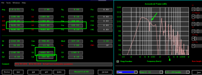
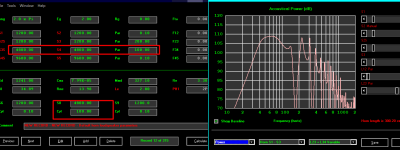
") .
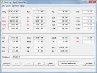
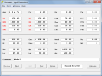
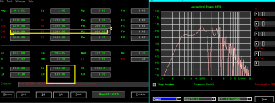
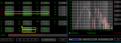
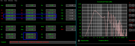
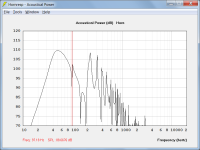
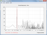
.In your examples the axial lengths of cylindrical segments H1, H4, H5 and H7 as shown in Attachment 1 are very short, making them effectively non-existent. A null will appear in the response when the dimensions of segments H2, H3 and H6 are such that a phase cancellation occurs when the H3 and H6 outputs combine, as shown in Attachment 2. At that frequency there will be a rapid change in phase, and hence group delay, as shown in Attachment 3.
Adjusting L23, L34 or L78 in the Loudspeaker Wizard will shift the frequency of an existing null, or alternatively, depending upon the lengths specified, insert one.
Attachments
Your guess is as good as mine...
The analysis of the paraflex acoustic circuit is quite complicated, making it difficult to identify what mechanisms are actually causing the notch in your test examples. I suspect that about the best that can be done is to adjust the different parameter values in the Loudspeaker Wizard to see how they affect the frequency and amplitude of the null, and try to come up with a plausible theory that explains the results being observed.
My primary focus is on making sure that Hornresp analyses the simulation models correctly so that the results produced are valid. The reasons for those results being what they are, I leave for others to decide.
The analysis of the paraflex acoustic circuit is quite complicated, making it difficult to identify what mechanisms are actually causing the notch in your test examples. I suspect that about the best that can be done is to adjust the different parameter values in the Loudspeaker Wizard to see how they affect the frequency and amplitude of the null, and try to come up with a plausible theory that explains the results being observed.
My primary focus is on making sure that Hornresp analyses the simulation models correctly so that the results produced are valid. The reasons for those results being what they are, I leave for others to decide
.Again one question which is not strictly horn-resp related.
I've been taught that in the far field, any loudspeaker has a round propagation wave. On the other side I keep reading that unlike direct radiation speakers (or other types of horns), only multicellar horns have a round propagation wave.
I assume this apparent contrast between the two notions, may have to do with the different propagation of arrays vs point source, and WHERE the transition between far field and near field actually happens with different types of loudspeakers, in relation to the actual radiating surface and shape, which is quite different in arrays and particularly in multicellulars when compared to the rest.
My assumption may well be wrong so hopefully someone will shed some light on the subject and clarify the matter.
Hi David,
first things first thank you for your great program.
I want to simulate a TML with two chassis drivers. One driver should be on a fifth, the other driver should be on a third of the TML.
I think I remember simulating this before. But can not find the settings, maybe someone can help. Thanks very much.
Christoph
Hi Christoph,
Hornresp models multiple drivers as a single equivalent composite unit.
If the first driver is at one fifth distance and the second is at one third, then for the purposes of the simulation the single equivalent unit should be placed halfway between the two, that is at four fifteenths distance.
To illustrate, if the transmission line is 120 cm long then the first driver would be at 24 cm (1 / 5 * 120) and the second at 40 cm (1 / 3 * 120). The composite driver (2P or 2S) should therefore be specified as being at 32 cm (4 / 15 * 120).
Kind regards,
David
- Home
- Loudspeakers
- Subwoofers
- Hornresp