"To directly set a slider control to a specified value, key in the value and then press Enter while the control has the focus."
Further to the above statement, please note that it is also possible to quickly move through a slider control value range by simply pressing and holding the Home or End key, while the slider has the focus.
Kind regards,
David
Anyone has info or a link to help me understand how to use hornresp to model a synergy horn?
Hi almino,
Hornresp can be used if the front loaded horn and offset driver horn components are considered separately. Use AkAbak if you wish to model the synergy horn as a single complete system.
Google-search on the keyword phrase:
Hornresp synergy horn tutorial
For starters:
DIY Synergy horn
Google is your friend...
") .
.Kind regards,
David
DIY Synergy/Unity spreadsheet
From one of the best, most detailed real to life versions.
Includes a spreadsheet to do the dirty work.
This isn't an approximation.
This is the real Article.
From one of the best, most detailed real to life versions.
Includes a spreadsheet to do the dirty work.
This isn't an approximation.
This is the real Article.
Hi Andrew.
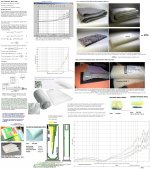
I do sim just with speaker wizard, it is a very nice start and so i come out where I try not to big, the low end is because of the port support I gess, it
is a mass loaded TL..
Alone the port is different, this is a separate simmed jet port, normally it is a straight port, for noise problems I did sim twice different boxes so I get port length of the jet port..
http://www.diyaudio.com/forums/subw...d-transmission-line-od-ml-tl-design-bj-2.html
I do not now what the long pipe does, but for low and not to small port it is needed.
Picture one I did use only vtc to get volume and so I can sim that port, see link why and how.
Hi Kees,
When reading the previous postings of this thread to search for additional HR update information:
http://www.diyaudio.com/forums/subwoofers/119854-hornresp-452.html#post3934884
I found and read your Posting #4515, + submitted Pictures:..
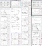
Couldn't resist to rework your Simulation a bit: See the First of Pictures:I disagree with your statement on predictions using 'Stuffing' and there are a lot of available 'specialized Programs' that deals with the acoustic impact of placing 'Stuffing' in any type of Ducts (I have quite a few that even calculates the 'Home' absorption/attenuation as well):
Good predictions of the impact on 'Sub' designs can be done by using HR if proper Material data is known, that is if the correct Flow Resistance is known and used in the Reality.
The impact of almost any low Density type of 'Fiber-fill' is fairly constant versus frequency below ~100 Hz and only requires a simple linear scaling depending on what 'Fill' material is in use.
If not a Rayl/number is available:
Just Scale the different α below ~100Hz to a known Fiber fill in Rayl/m if you have the absorption measurements placed on the same plot like the absorption comparison I've made in the second/third of Pictures(Notes):
For frequencies above (~100Hz) where the 'Fill' Materials have different α (Absorption Coefficient):
In the Reality: Smoothing the Ripple will return a different frequency attenuation profile in a Quarter-Wave Design.
The prediction of the 'Damping' effect becomes more complex, but only above ~1 kHz where the α is either constant or declines:
As the α Data is typically considered(and accurate) for frequencies below 1 kHz in a Quarter-Wave Design, you need the result from the 'Material' α and the Flow Resistance to smooth the FR if Stuffing an entire Section Volume.
The chosen amount of Damping material, i.e. the Flow Resistance should be applied cautiously without affecting the SPL too much, as the damping effects will be summed if using Sections in series.
Use different Layers thinned out Fiber-fill and if some sort of Felt is partly covering the internal Walls near the Throat end: Densities are typically > 3000 Rays/m(Felt) combined with Layered Materials(Shifting Densities) always allowing a free Air Path from the in HR S2 Area to S4(S5) Area(s).
My use of Pillow-fill in HR simulations:
1: 307 Rayl/m = IKEA Pillow-fill teased maximally. If thinned out more, i.e. to
2: 153.5 Rayl/m the fill must be secured by using a kind of Bag, = Maybe a sort of Insect Net.
3: If further thinned = 77 Rayl/m cross bracing is necessary(many thin threads).
The target Density for my teased Pillow-fill investigation was to establish the minimum(*) that can be used for slightly Flow-damping a Port in a ML-TL prone to Half-wave resonances or to be inserted in the throat compression area of a TH, T-TQWT, T-QWP or any other Quarter-wave Design requiring a minimal absorption and a low amplitude loss at frequencies below ~100 Hz but obviously more above ~150Hz: in my previously submitted contribution(elsewhere) for Pillow-fill: Look for the elevated part of the Absorption Curve.
This beside the always Driver beneficial reflex Wool-damping(1/8“-1” high Rayl/m material) of the nearby walls when the Compression Ratio Sd/S2 is < = 3:1, at least within the Volume where the Higher Order Modes are expected to occur, IE. the Compression Volume that typically is about 3x the mean CSA Diameter(**) centered at S2.
In a Kundt's Tube:
This is the Volume where Mic. Measurements give totally random results(uncorrelated) if the position is even moved slightly(mm) and is never used for Standard Measurement of Acoustic Materials.
(*) A traditional TL, OD or not, is stuffed in the entire Length using a Fibrous Material that provide adequate attenuation(α) of Mid/High frequencies and with a DC Flow Resistance that is attenuating the Volume-Velocity in order to a targeted Value more or less Aperiodic..this is seen in a Driver Electrical Impedance Plot as affecting the lowest in frequency visible Amplitude Peak.
(**) The Diameter(Area Aspect Ratio no more than 2:1)(***) that defines the upper frequency cut-off is d(m)= Kc/fu where fu(Hz)= upper f limit; K=0.586;C= speed of sound in a circular tube in m/sec. If the CSA is Rectangular d is defined as the largest dimension of the CSA (Area Aspect Ratio no more than 2:1) and K is = 0.5.
***Larger Aspect Ratios should IMO be avoided as 2p/3p waves will extend the compression Volume virtually to be longer before clean Plane-Waves are formed and those HOM's(High Order Modes) Waves of which some of course are evanescent before reaching the Mouth (Most are further absorbed by the addition of Damping Materials like in a TL, T-TQWT/T-QWP) but may slip through the entire box:
Manifesting in an easily heard characteristic footprint-sound= Low-Fi despite the box has many folding's(****) designed for portability like those high compression Ratio ( High Power 'Cone- Shredders') designed TH's this Forum is nearly flooded with Diet Pill Testosterone.
(****)Here= Upper FR Phase Scramblers where the Virtual Length Modulators are defined by the different frequency miss-tuning induced by the random 'Bends or Folding definition in use
.
The TF: s of these anomalies can be calculated and multiplied to a HR simulation TF or added to an AKAbak Script Sub Routine and compared to a Real-Life measurement.
Near very congruent curves are achieved if overlapped on a graph.
But there are awkward comments everywhere in HR User Threads that judges the frequency curves not reliable:
Nonsense, IMO This type of pleading is only revealing an ignorant layman:
A Newbie in applied Acoustics that lacks fundamental understanding of Math and Wave Physics but is a whopper when it comes to wishful thinking of an odd self-inflicted outcome after a HR Tombola run.
b
PS: I've seen a lot of submitted Photos to diyAudio: Showing in random minute tossed non homogeneous Stuffing 'Clouds' of Material into Vented types of Boxes or in a T-TQWT and T-QWP:
I MO I find this approach totally unacceptable if blameless SQ performance is the intention.
To add Stuffing into a Box in order to secure a proper performance takes time(maybe Hours) and care as sometimes a repetitive approach with mandatory confirmation Measurements showing it's done right before closing the Enclosure for good.
A few Links of good reading:
http://www.gearslutz.com/board/atta...ens-corning-705-707-king-4610-4617-seddeq.pdf
http://www.acoustics.asn.au/conference_proceedings/AAS2012/papers/p55.pdf
http://www.roush.com/Portals/1/Downloads/Articles/AutomotiveSoundAbsorbing.pdf
Extra:
Effective wave-number of a conical waveguide:
http://www.phys.unsw.edu.au/jw/reprints/Kulik.pdf
Attachments

But there are awkward comments everywhere in HR User Threads that judges the frequency curves not reliable:
Nonsense, IMO This type of pleading is only revealing an ignorant layman:
A Newbie in applied Acoustics that lacks fundamental understanding of Math and Wave Physics but is a whopper when it comes to wishful thinking of an odd self-inflicted outcome after a HR Tombola run.


I have made very many boxes that I designed in Hornresp.
I can say unequivocally that the sims are accurate.
At times astonishingly accurate.
Trust the software. Plain and simple.
F9 suddenly didn't work anymore in Chamber.
It would have been a bug if it did
.Hornresp Update 3470-140529
Hi Everyone,
CHANGE 1
With a tapped horn, the Tools > Chamber Type menu was displaying the Throat Adaptor menu command when it should have been showing the Throat Ported menu command. This has now been fixed.
CHANGE 2
With the inclusion of the Filling option in the Loudspeaker Wizard, some status messages were being hidden behind the Tal1 slider at the bottom of the form when four segments were specified. This has now been fixed.
Kind regards,
David
Your fixing bugs in areas I didn't even know there were bugs.
Hi Mark,
I am pretty fussy, and it also helps to know where to look
.I will be making another minor 'tweak' soon - nothing significant though.
(Much more time has been spent on getting the Hornresp user interface to work correctly than on coding the actual simulation calculations).
Kind regards,
David
Hi David,
I just ran through a design for a corner subwoofer, and was again amazed at how easy it has become to arrive at a workable first simulation.
http://www.diyaudio.com/forums/subw...p-newbie-design-build-pair-corner-subs-2.html - Post #18.
I have build - or tried to build - transmission lines in the 1970s, and build measure, curse, build again just was not a lot of fun at all.
Thanks,
- Home
- Loudspeakers
- Subwoofers
- Hornresp