Hi everyone,
I got the sub from a friend and thought i could drive it with the NAD, which has quite a respectable output (150 wpc, 400 wpc bridged into 8 ohm).
My first attempt with the 2ohm DVC in series to give a 4 ohm load and the NAD bridged did not give much output and power delivery, had to crank up the sub level on the receiver to get it level with the mains. The other possible conection would be to connect each channel of the NAD to a 2ohm voice coil separately. I did an estimate of the power delivery (with a limited understanding). Would option 1 or 2 be better ?
Option 1 : 4 Ohm series voice with bridged NAD
Assume 10V rms input, the current flow is
I1= V/R = 10/4 = 2.5A
Power, P1 = VI = 10*2.5 = 25 watt
For a bridged amp, am i right to say that each channel is driving 5V and 1.25A, or should it be 5V and 2.5A into a 2 ohm load (half of the 4 ohm total)?
Option 2 : 2 ohm driven by each channel
Assume 10V rms in each channel, current in each voice coil is
I2 = V/R = 10/2 = 5 A
Power, P2 = 2*VI = 2*10*5 = 100 watt
It is 4 times the power delivered to the sub at the same V rms input!!! Is this correct?
Should i wire it up via option 2? Is there any other aspect that i overlooked?
Thanks a lot for the advise and suggestions!!
Sorry for double posting...some additional info on the sub.
It is currently in a 1.25 cuft sealed box per suggested design by Rockford. From my tests, it is not really fantastic, could be due to the connection issue to the amplifier.
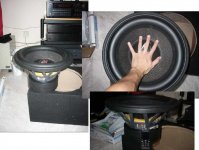
Belief this sub is basically a car audio SPL monster, it weights like 20 pounds and can handle 1000 watt continuous, 2000 w peak. I bought it thinking i could make it into the ULTIMATE transmission line sub, with a 15 inch driver and 19mm of linear excursion.
So that's the story, hope i could get some insights on the connection issue, and hopefully get some help on designing a transmission line for this monster of a sub. Spec attached.
It is currently in a 1.25 cuft sealed box per suggested design by Rockford. From my tests, it is not really fantastic, could be due to the connection issue to the amplifier.
Belief this sub is basically a car audio SPL monster, it weights like 20 pounds and can handle 1000 watt continuous, 2000 w peak. I bought it thinking i could make it into the ULTIMATE transmission line sub, with a 15 inch driver and 19mm of linear excursion.
So that's the story, hope i could get some insights on the connection issue, and hopefully get some help on designing a transmission line for this monster of a sub. Spec attached.
Attachments
I guess i kinda answered my own question, waiting for the weekend to try out connection 2 channel each driving a 2 ohm voice coil.
Have been messing around with the TML design. Is there any optimum T/S parameters for a TL?
This one has Qts = 0.38 and Qes = 0.41, Vas 3.5 cuft Fs 22 Hz. For a 22 Hz tuning, MJK's site suggests maybe 120 in or 10 feet, with a 3 to 1 taper. Now this this has 384g (almost 1 pound!!) of moving mass and kicks like a mule with its current sealed box. I'm thinking of a down firing design to get as much mass (the whole box!) the driver as possible, best would be a 10 foot high, 15inx15 in at the driver tapering down to 15x5in at the end.
MJK has stopped free access to his models, is it still available anywhere? Would be awesome if i could simulate the response in a 22 Hz 10 foot TML.
I'm currently using a 12 in sub, Vibe alpha 2.
http://www.homecinemachoice.com/cgi-bin/displayreview.php?reviewid=5229
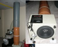
I modified it into a transmission line by attaching a 12 in diameter 76 inch long PVC pipe ( cut a hole in the top of the enclosure hehe). The driver is downward firing and is aligned with the pupe.The height is no rocket science, limited by the height of my ceiling, but i reckon its about 40 Hz tune including the height of the box.
It sounds great, no boomy and congested sound. and i can't wait to hear how the rockford sounds in a proper TL.
Have been messing around with the TML design. Is there any optimum T/S parameters for a TL?
This one has Qts = 0.38 and Qes = 0.41, Vas 3.5 cuft Fs 22 Hz. For a 22 Hz tuning, MJK's site suggests maybe 120 in or 10 feet, with a 3 to 1 taper. Now this this has 384g (almost 1 pound!!) of moving mass and kicks like a mule with its current sealed box. I'm thinking of a down firing design to get as much mass (the whole box!) the driver as possible, best would be a 10 foot high, 15inx15 in at the driver tapering down to 15x5in at the end.
MJK has stopped free access to his models, is it still available anywhere? Would be awesome if i could simulate the response in a 22 Hz 10 foot TML.
I'm currently using a 12 in sub, Vibe alpha 2.
http://www.homecinemachoice.com/cgi-bin/displayreview.php?reviewid=5229
I modified it into a transmission line by attaching a 12 in diameter 76 inch long PVC pipe ( cut a hole in the top of the enclosure hehe). The driver is downward firing and is aligned with the pupe.The height is no rocket science, limited by the height of my ceiling, but i reckon its about 40 Hz tune including the height of the box.
It sounds great, no boomy and congested sound. and i can't wait to hear how the rockford sounds in a proper TL.
Attachments
...Would be awesome if i could simulate the response in a 22 Hz 10 foot TML...
I would prefer a folded 6:1 TL tapering in order to keep both driver and the terminus close to the floor.
b
1(1)
Attachments
Wow!!, thats awesome. At work now and i can't wait to get back home to look through the sheet properly!! Thanks a lot bjorno!!
Does it make a difference to the simulated response if the 2 voice coils are each driven separately instead of connected in series?
I also noticed the Xmax was 13 mm, should be 19 mm? Guess it only affects the max output.
Regarding the impedance curve, with the voice coils in series to give 4 Ohms, impedance from the chart for the 6:1 taper ranges from 10 to 35. Is that Ohms seen by the amp, or it is acoustic impedance of the system? Can i drive it in parallel for a 1 ohm load? Might fry my NAD lol.
Anyway, the frequency response looks pretty strong down to 20 Hz, in other words awesome!!
Is this a good driver for a TML design in your experience? I was quite worried as it was supposed to be a car audio SPL driver, not too sure how the sound quality will turn out, or does it not matter as that depends on the T/S parameters ?
How does it compare with, say the Dayton 15 " sub from Parts Express in a similar optimised TML ?
Lastly, any chance of getting a copy of the mathcad sheets? PM or email me, i will be ever grateful!
cheers!!
PS: I'm so excited if you can't tell already!
Here's a picture of the sub for scale. Its huge!!
Bjorno, i have a couple of question if you don't mind. Looking at the acoustic impedance chart in your calculation, i'm assuming the max impedance corresponds to the tuning frequency. That means the 120" 6:1 taper TML is actually a 13Hz tuning? Per my calculations, 120 " should give about 28 Hz with no taper, and close to maybe 20 Hz with the 6:1 taper?
Is there any benefit of increasing the line length to 12 or 14 feet or even more? I'm contemplating making it into a side table of some sort, so a single fold, side firing config would give a length of about 6-8 feet. I could even place it in front as a TV table, between the main speakers. Has anyone tried that before? using the subwoofer as a TV table between the mains?
I'm thinking it should kind of be in the optimum location. Provided your mains are about 3-4 feet in from each side wall, and there is about a foot between the sub and each main speaker.
Adios for now, can't wait to hear what 20Hz at 110 db sounds or feels like.
Attachments
Answers to posting # 5:
Yes it does, look at picture 1(2)
X-max peak is 19 mm but x-max RMS based on 0.74” = 2.54 x 0.74 = 18.8796 mm peak = 13.29 mm Rms = rounded off = 13.3 mm Rms.
Yes it’s the amplifier complex load seen, that is what’s really counts, forget nominal advertised loads like 4,8, 2, 1 and so on, focus on your XO: ed maximum/minimum load and compare with the amplifier capability to drive that load.
I don’t recommend you to load your amplifier with less than 4 ohms, i.e. use the coils in series and if you choose to crossover at 50 Hz – 60 Hz max, then you can safely use the bridged mode of your amplifier.
Agree…
There are a few car drivers I like but if I would choose one depends on the available data that must be complete like the one for the 15 in Rockford and preferably including a Dumax report.
I’m avoiding all the others as they mostly turn out to be of crappy designs when examined, not suitable for use home use.
First I don’t use the aberration TML for a traditional TL but only for quarter-wave based speakers using (a) separate port(s) where the tuneable port air mass can be separately defined as for a ML-TL mass loaded transmission line.
This is what I can show you, draw your own conclusions: picture 2(2)
I don’t use the older sheets anymore and I recommend you to get MJK: s MathCAD vastly improved sheets from:
http://www.quarter-wave.com
The yearly fee is only US $25/year for a DIY user.
posting #6:
Yes.
No, if you do you will loose the possibility to damp the TL properly; the speaker turns in to an empty ripple rich quarter-wave pipe.
b
1(2)
…Does it make a difference to the simulated response if the 2 voice coils are each driven separately instead of connected in series?…
Yes it does, look at picture 1(2)
…I also noticed the Xmax was 13 mm, should be 19 mm?
Guess it only affects the max output…
X-max peak is 19 mm but x-max RMS based on 0.74” = 2.54 x 0.74 = 18.8796 mm peak = 13.29 mm Rms = rounded off = 13.3 mm Rms.
…Regarding the impedance curve, with the voice coils in series to give 4 Ohms, impedance from the chart for the 6:1 taper ranges from 10 to 35. Is that Ohms seen by the amp, or it is acoustic impedance of the system?…
Yes it’s the amplifier complex load seen, that is what’s really counts, forget nominal advertised loads like 4,8, 2, 1 and so on, focus on your XO: ed maximum/minimum load and compare with the amplifier capability to drive that load.
…Can i drive it in parallel for a 1 ohm load? Might fry my NAD lol…
I don’t recommend you to load your amplifier with less than 4 ohms, i.e. use the coils in series and if you choose to crossover at 50 Hz – 60 Hz max, then you can safely use the bridged mode of your amplifier.
…Anyway, the frequency response looks pretty strong down to 20 Hz, in other words awesome!!…
Agree…
…Is this a good driver for a TML design in your experience? I was quite worried as it was supposed to be a car audio SPL driver, not too sure how the sound quality will turn out, or does it not matter as that depends on the T/S parameters ?…
There are a few car drivers I like but if I would choose one depends on the available data that must be complete like the one for the 15 in Rockford and preferably including a Dumax report.
I’m avoiding all the others as they mostly turn out to be of crappy designs when examined, not suitable for use home use.
…How does it compare with, say the Dayton 15 " sub from Parts Express in a similar optimised TML ?…
First I don’t use the aberration TML for a traditional TL but only for quarter-wave based speakers using (a) separate port(s) where the tuneable port air mass can be separately defined as for a ML-TL mass loaded transmission line.
This is what I can show you, draw your own conclusions: picture 2(2)
…Lastly, any chance of getting a copy of the mathcad sheets? PM or email me, i will be ever grateful!cheers!!…
I don’t use the older sheets anymore and I recommend you to get MJK: s MathCAD vastly improved sheets from:
http://www.quarter-wave.com
The yearly fee is only US $25/year for a DIY user.
posting #6:
…That means the 120" 6:1 taper TML is actually a 13Hz tuning?…
Yes.
…Is there any benefit of increasing the line length to 12 or 14 feet or even more?…
No, if you do you will loose the possibility to damp the TL properly; the speaker turns in to an empty ripple rich quarter-wave pipe.
b
1(2)
Attachments
Bjorno,
I noticed the hump in frequency response between 30-50Hz for 1 coil/amp connection; is there any way of smoothing it out since i'm planning to drive the sub this way?
I know you recommend using the 2 coils in series to give a 4 ohms load, however this brings me back to my first question regarding power delivery. I don have satisfactory results with a 4 ohm load in the 1.2 cuft sealed box that came with the box. Any idea what could be the problem? I thought 88 db/watt sensitivity is pretty normal, and the 2600A is no slouch. Was very puzzled at the lack of power into the 4 ohm load. Car audio forums talk about needing at least 1000W to 'wake up' this driver.
The electrical impedance curves peak at 29 Hz, instead of the 13 Hz peak for the acoustic impedance. Is the tuning 29Hz or 13 Hz?
Also, the electrical impedance peaks are quite 'sharp', i have read that well designed transmission lines are characterised by very mild impedance peaks due to the nature of the design.
Regarding the 13.3 mm Xmax at 1Hz limiting input power to 70 W rms, does it make a difference if a rumble filter is implemented at about 12Hz? Does it give the sub even more headroom for higher SPL from 18-80 Hz?
Now that there's quite a bit of details in the design, i hope to hear any other comments from the community. Thanks a lot.
Rumble filters
What is the benefit of applying rumble filters in the 10-15 Hz range? Does it increase amp and driver headroom? 130 dB at 30Hz? : ))
How would i do it if i were to use a passive crossover? Would need a steep slope, maybe 4th order? 1 filter for each 2 ohm voice coil?
Also, would it be better to drive the sub with the NAD power amp, or to get the 1000W parts express plate amp? Which would give more real watts? The PE plate amp is rated at 1024 watt into 4 Ohms, not sure if this is RMS or peak. The NAD can drive 600 W peak into 2ohm peak per channel.
rhapsodee said:Bjorno,
Regarding the 13.3 mm Xmax at 1Hz limiting input power to 70 W rms, does it make a difference if a rumble filter is implemented at about 12Hz? Does it give the sub even more headroom for higher SPL from 18-80 Hz?
What is the benefit of applying rumble filters in the 10-15 Hz range? Does it increase amp and driver headroom? 130 dB at 30Hz? : ))
How would i do it if i were to use a passive crossover? Would need a steep slope, maybe 4th order? 1 filter for each 2 ohm voice coil?
Also, would it be better to drive the sub with the NAD power amp, or to get the 1000W parts express plate amp? Which would give more real watts? The PE plate amp is rated at 1024 watt into 4 Ohms, not sure if this is RMS or peak. The NAD can drive 600 W peak into 2ohm peak per channel.
- Status
- This old topic is closed. If you want to reopen this topic, contact a moderator using the "Report Post" button.
- Home
- Loudspeakers
- Subwoofers
- Driving a Rockford 15in DVC sub with a NAD 2600A