Hi Jims,
Your better off mounting the BD139 to one of the output transistors. BTW I'm working on a new version of my board that allows mounting U3,U4 to the main heatsink.
While I'm at it if there are any other changes you'd like me to make please let me know.
Best regards,
Al
Your better off mounting the BD139 to one of the output transistors. BTW I'm working on a new version of my board that allows mounting U3,U4 to the main heatsink.
While I'm at it if there are any other changes you'd like me to make please let me know.
Best regards,
Al
recommendations
Hi
Aside from my self-imposed problems with the BD139, the board is very nice.
The only big improvement, IMHO, would be to have room for a bigger C1. Coming from the tube world I have some nice caps, and bypass caps, that I would like to try. Also for the transformer input, can you space them in a row with 5mm spacing (I think) so that we can use the standard 3pos pheonix terminal blocks, like the ones you use on the speaker outputs. I also remember that one of the resistors near the inputs was a very tight fit and I had to stand it on end. I am at work now, and can't remember which resistor it was. Oh and the speaker grounds were difficult to solder in between the big powersupply caps and C18 . Now I am nitpicking.
JimS
back to my problem
Hi
To recap. I was blowing fuses on the negative side of one of my amps.
So I removed U3, U4 and Bd139. U4 was bad, U3 and the BD139 were OK. I matched a new set of U3 and U4 and replaced the BD139, mounted on U3. I powered up and did not blow the fuse. I biased to 10mv across both resistors and found I was getting 70mv DC offset on the outputs. On my good amp I get 3mv across the outputs. I suppose I have another bad transistor(s). Any ideas as to which ones to replace next or should I just replace them all on the negative side?
Thanks
JimS
Hi,
70mV is not that bad having changed some of the transistors.
Is there an offset adjustment? It needs adjusting and if you can do that within the range of the adjuster then your circuit is probably OK.
Do the offset measurement with the input shorted and with the output open circuit. Then check how it changes as the amp warms up.
oops, my thinking hat must have dropped off in the snow.MikeB said:Andrew, SymAsym does not have an offset adjustment. /B]
Hi JimS
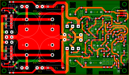
Thanks for suggestions. I moved the input terminals so now you can
use Phoenix type terminals for the transformer inputs, and added vias to both sides of the Wima input cap to accommodate a larger cap.
I also added a couple leds after the fuse that serves as a blown fuse indicator, and holes to mount U3,U4,U5,U6 to the main heatsink. I tried to figure a way to fit a hole on the board for mounting the BD139 to the main heatsink but it's way to tight. So for the BJT version the BD139 still needs to be mounted to one of the output transistors.
Here's my latest board with all the changes mentioned above. This is my mosfet version of SymAsym. The BJT version is basically the same accept I have to swap to pins on each output transistor.
Best Regards,
Al
Attachments
Hi,
the input arrangement of the 3pair Leach clone done by Jens is almost ideal.
Three pads at 0.1inch centres;
middle is AC coupled input,
to left side is DC coupled input (bypassing the input cap),
to the right side is audio ground.
Now the clever bit.
Put in three PCB pins which act as jumper poles.
Solder the screen to the back of the audio ground pin.
Solder the signal core to the back of the middle pin.
Now use one of those 0.1inch jumpers.
Jumper attached to just one pin = AC coupled input.
Jumper audio ground to middle pin = shorted input for testing.
Jumper audio ground to cap bypass pin = DC coupled input.
And all this uses less space than the current arrangement.
new board
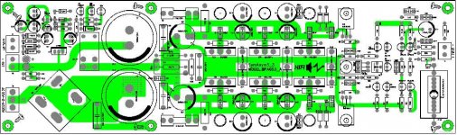
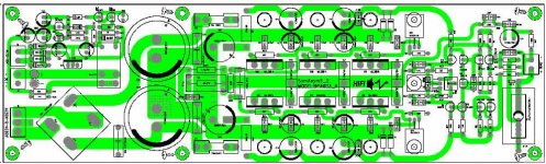
Looks nice.
Couple of ideas:
1)Can you rotate c18 90 degrees and move it to the side of the speaker grounds to give greater access to the speaker grounds from the front of the board? It is tough to solder and remove with C18 in front.
2)For the BD139, what if you move c18 as per above, then you can then move c6/r26 and speaker-out closer to the big caps. Then you can put a hole in the middle of the board for mounting the bd139 directly to the heat sink.
3) Also, bypass holes for C1 would be nice, even if you have to attach below the board. I would like C1 spacing even wider, but it looks tight. However increasing the whole size for C1, might make it easier to remote mount a larger cap.
Built another board yesterday, testing tonight.
JimS
little problem ...
Hi all,
I'm finishing my amp..
I want to put 2 mono pots because of the low power of my actualy drivers (fullranges)
In Pavel site, he recommends 22k pot ( entry ) .
I've try this, but i loose bass.
My cd is connected to the amp. (no pot on the cd driver).
Is the value different with the aaksym ?
Thanks.
![20070626_5c2cd051699eaf5b1c04d58bfrwiwpiv[1].jpg](/community/data/attachments/102/102937-1ad20a921d66a8d71ac287b4d59de7af.jpg)
CeeVee said:....and this.
How do you bolt the output heatsinks on that arrangement?
- Status
- This old topic is closed. If you want to reopen this topic, contact a moderator using the "Report Post" button.
- Home
- Amplifiers
- Solid State
- Symasym 5.3 "AAK model" builder's thread