Re: Tech help for Audio Analogue
But it is obvious that Bonsai recommends you the Solid State forum in which is found this thread "Post your solid state pics here". You must open a new thread in this forum here, with your query. It is so simple!
VintageAmp said:Thanks,
your explaination would explain the lack of response. This is a complicated issue where a schematic would help. It does seem this amp is not very well known. Which thread would you recommend?
But it is obvious that Bonsai recommends you the Solid State forum in which is found this thread "Post your solid state pics here". You must open a new thread in this forum here, with your query. It is so simple!
please notice
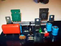
...... a very strange thing .... in this project used bc546 .... for ltp and curent source , ( matched pair with thermal junction ) which bc 546 i got from a shop i dont remember ( will track down though ) and the logo was : BC546-B and down under the number 351 was printed .
suprizingly all of them had a hfe of .......351 very very closly to each other .....
Attachments
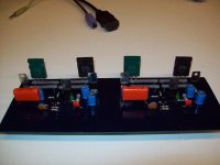
nelson pass a40 ....
ready and working allright but it will have to freeze for a while before get ready to be a ready made device since no decent tip142-147 are found in the Greek market yet and then on the other hand i dont really wana go for cans ..... too much mechano to do that i am not up to these days
also another reason to freeze this is that the mosfet used for a current source is almost impossible to get ( as we speak only one resistor+cap is used ) so this part needs to be redesigned ....
the pcb is the original but i am actually tempted to make my own since i really dont like outputs wired to the pcb ..... this is something i would never do .....
regards sakis
PS .... it measures pretty fine but still havent heard anything from it ....i dont wana spoil my ears before everything very ready first ..... ha ha ha
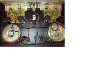
Attachments
same thing as above
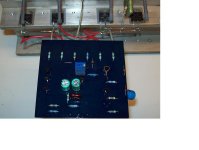
my easter toy ....as a dual mono version
i apologize for the construction since most of the construction i make looks really nice but this particular one was originally builted as Legend 4 but failed .... for about 20 times and then reconstructed again and again and again till i decided to do something finally useful with it ....
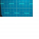
here is the pictures and also scope readings ....with the first one at 10 khz and the second one .....at 100khz ..... nice baby heeee
my easter toy ....as a dual mono version
i apologize for the construction since most of the construction i make looks really nice but this particular one was originally builted as Legend 4 but failed .... for about 20 times and then reconstructed again and again and again till i decided to do something finally useful with it ....
here is the pictures and also scope readings ....with the first one at 10 khz and the second one .....at 100khz ..... nice baby heeee
Attachments

My toys during Greek Easter
Hi Sakis
×ñéóôïò Áíåóôç!
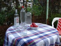
In the attached picture are my toys for Easter. In the left, a bottle of tsipouro (very good, its price is 10,5 euro/0,7Lt) in the middle a bottle of cold water, and in the right a can of home made tsipouro (gift to me).
Ahahaha!
For the foreigners in this post, the red egs are for cracking, a Greek custom of Easter.
Fotios
Hi Sakis
×ñéóôïò Áíåóôç!
In the attached picture are my toys for Easter. In the left, a bottle of tsipouro (very good, its price is 10,5 euro/0,7Lt) in the middle a bottle of cold water, and in the right a can of home made tsipouro (gift to me).
Ahahaha!
For the foreigners in this post, the red egs are for cracking, a Greek custom of Easter.
Fotios
Attachments
Cal Weldon said:Feel free to use this thread to post your DIY efforts.
Hi Guys
I'm totally new here and my amp will look funny in comparation with every other posted here.
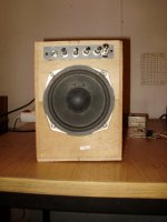
This my first guitar amp that I made and it is based on tda2030 IC.
Preamp is a fet version of fender blackface.
Speaker is a 15W 4 ohm which i took out from a portable CD player.
That pretty much says it all!
Cheap,simple and good enough for practise until I buy myself a decent guitar amp.

Attachments
Hi, all!
Here is one of my amps (Creek 4330 clone):
Here is one of my amps (Creek 4330 clone):
An externally hosted image should be here but it was not working when we last tested it.
An externally hosted image should be here but it was not working when we last tested it.
An externally hosted image should be here but it was not working when we last tested it.
An externally hosted image should be here but it was not working when we last tested it.

FastEddy, thanks!
The main board is designed by Creek Audio (I just copy layout from original, and replace a few components ). The design of other PCBs is mine.
And here is one more amplifier (even in the process of assemblage);
The old version of PCB:
and the latest version:
This is the "WP2006", 200W output at 4Ohms, with DC protection on board in the last version. The design of PCB is also mine.
The main board is designed by Creek Audio (I just copy layout from original, and replace a few components
). The design of other PCBs is mine.And here is one more amplifier (even in the process of assemblage);
The old version of PCB:
An externally hosted image should be here but it was not working when we last tested it.
An externally hosted image should be here but it was not working when we last tested it.
An externally hosted image should be here but it was not working when we last tested it.
An externally hosted image should be here but it was not working when we last tested it.
An externally hosted image should be here but it was not working when we last tested it.
and the latest version:
An externally hosted image should be here but it was not working when we last tested it.
An externally hosted image should be here but it was not working when we last tested it.
An externally hosted image should be here but it was not working when we last tested it.
An externally hosted image should be here but it was not working when we last tested it.
This is the "WP2006", 200W output at 4Ohms, with DC protection on board in the last version. The design of PCB is also mine.
 !!
!!It's PEH200 type, are they liquid?I hope those big caps arent rifa liquid types

- Home
- Amplifiers
- Solid State
- Post your Solid State pics here