It does matter.
The top row of devices will run much hotter than the bottom row devices.
10degrees will make a big difference to temperature de-rated SOAR, if you are running at Tc=70°C that becomes 80 for the upper row.
If it were Tc=50°C that became 55, then there is not much difference.
The top row of devices will run much hotter than the bottom row devices.
10degrees will make a big difference to temperature de-rated SOAR, if you are running at Tc=70°C that becomes 80 for the upper row.
If it were Tc=50°C that became 55, then there is not much difference.
Last edited:
Thank you for kind words
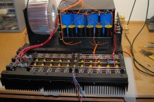
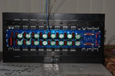
few more pics
And yes , its K_R_E_L_L__K_S_T_100 amp clone
Was it worth - YES
Wow. Absolutely fabulous. I salute you.
")
the Krell Clone above
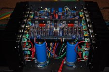
The TO-3 output devices of the Krell are mounted on an L-shaped heat spreader, with a pretty sizeable side that mounts to the heatsink.
Heat travels through aluminum much faster than from alloy to air, a large part of the dissipation will be conveyed to the bottom part of the heatsink.
Does mean that the hottest area is at the top, but also implies that the electrolytics are located at the least hot location.
The heatsink will not be the most efficient, but for a class AB power amplifier that will not be the first priority.
Lots of air around the electrolytic cans should always be, imo.
Are the PCBs available for purchase? If yes, where and how much?
Thank
It has no PCB available and 1 more thing is the complication, regarding less space I have to deal with hard-wiring as well.

Hi again
thank you for comments
Amplifier is 100W/8 Ohms with 10 output transistors per channel
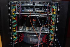
1KVA transformer located at bottom of the box
can work with 1 Ohm load
Used PCAD 2006 for PCB design and 3 months to digitize original
unit PCB and create drawings for box
Thank you
thank you for comments
Amplifier is 100W/8 Ohms with 10 output transistors per channel
1KVA transformer located at bottom of the box
can work with 1 Ohm load
Used PCAD 2006 for PCB design and 3 months to digitize original
unit PCB and create drawings for box
Thank you
Just an observation on above amplifier and the Krell Clone above, both seem incredible well implemented. There is one thing that strikes me as very odd, both place the output transistors on the very top of the heat sink, why not at the bottom ? which would yield a much more efficient use of the sink, heat does rise
Just my C2
Good Listening
Peter
Aluminum is pretty much the same temperature all over. Heat will travel down quickly. Technically they outputs are supposed to go in the middle of the heat sink.
Technically this is wrong................Technically they outputs are supposed to go in the middle of the heat sink.
The manufacturer datasheets generally give guidance on where to place components.
Some of the heatsink software allows one to discover where the optimal location/s is/are.
Last edited:
Techmically this is wrong.
The manufacturer datasheets generally give guidance on where to place components.
Some of the heatsink software allows one to discover where the optimal location/s is/are.
I've rarely seen any datasheet suggesting placement but when I have it's always been recommended to place them near the center so heat can radiate out in all directions evenly.
The optimum placement for single row given by the manufacturers is approximately 40% up from the bottom.
I think the actual figure is slightly less than 40%
They also give placement guidance for multiple rows. The bottom row is much closer to the bottom than the top row is to the top.
And I couldn't see my own typo !
I think the actual figure is slightly less than 40%
They also give placement guidance for multiple rows. The bottom row is much closer to the bottom than the top row is to the top.
And I couldn't see my own typo !
The optimum placement for single row given by the manufacturers is approximately 40% up from the bottom.
I think the actual figure is slightly less than 40%
They also give placement guidance for multiple rows. The bottom row is much closer to the bottom than the top row is to the top.
And I couldn't see my own typo !
Link ?? I have not drilled my Heatsinks yet.
So for 2 rows - not centered , but closer to the bottom ?
OS
When we place devices on a sink we do it symmetrically as it lays out nicely and allow for proper electrical connections, here is one example for TO3P devices. Ill post another image tomorrow for how we handle TO3 packages as well as TO220 which is pretty close to how this is done but with use of a PCB.
I recommend using non magnetic hardware like Stainless for the devices.
I recommend using non magnetic hardware like Stainless for the devices.
Attachments
Sorry I don't have any links.Link ?? I have not drilled my Heatsinks yet.
So for 2 rows - not centered , but closer to the bottom ?
OS
Both Avvid, Wakefield and another? have an app note that describes the optimum layout.
I have seen more, but it was such a long time ago.
If I remember nearly correctly, two rows are roughly 25% up and 60% up from the bottom. Note how close the upper row is to the middle.
Remember that the holes generally do not coincide with the centroid of the heat transfer interface, unless you use clamps.
If heat would be evenly distributed along the height H of a heatsink, devices would be placed at 25% and 75% H.
If heat distribution would have a triangular shape, max at the bottom, zero on top, devices would have to be placed at a little over 20% and just over 60% H.
(Divide a triangular area in two : top area = bottom area. Device placed in the centroid of each area. For a triangle e.g., at 1/3H from the bottom side)
Approximation of the heat distribution of a real heatsink will be a combination of both.
Part of the heat distribution area is rectangular shaped, with a triangular part superimposed.
So one device at some point inbetween 20+% and 25%, the other somewhere along 60+% and 75% of the height H.
That's under the assumption of an infinite width of the heatsink, and point sources of heat.
In reality, a heatsink has limited width and the contact area of power devices will be hot spots.
So the bottom one will be closer to 25%, and the top one closer to 60%.
(the mutual influence in the heatsink area inbetween the devices would still have to be accounted for)
Last edited:
Heres another couple of examples on how we place TO3P and TO3 devices, The TO3 is a two piece assembly consisting of one piece that holds the PCB and the transistors, which have a very large area that couples to the heat sinks.
Peter
Peter
Attachments
you should never mount transistors like its done with those TO3P devices.
2 separeted sinks with un-even amount of output devices. that will make the transistors run at un-even temperatures. Mount the whole set of transistors on one single heatspreder and mount the sinks on the heatspreder insted. like it's done with the TO3 devices.
2 separeted sinks with un-even amount of output devices. that will make the transistors run at un-even temperatures. Mount the whole set of transistors on one single heatspreder and mount the sinks on the heatspreder insted. like it's done with the TO3 devices.
- Home
- Amplifiers
- Solid State
- Post your Solid State pics here