MiiB said:LIneup
How will the circuit perform with 6 or 12 dB Gain. I suspect as you lower feedback performance will start aproaching normal figures.
Is it possible to have a compleate schematic with components and values showing then we can compare simulations with different toys.
Best
Michael
First.
Even if it maybe is not obvious from schematic,
the basic topology idea is the same as for Analog Devices AD797 opamp.
1. All gain is in first stage 2 transistors differential
2. Second stage is used to integrate the gain into one node
3. Third stage is a buffer
Analog Devices AD797 - Ultralow Distortion Ultralow Noise Op Amp
To answer your question, Michael.
I have no doubt my setup will produce very good figures
even at V-Gains of 2-4 or even 10.
Notice also, as this is a discrete,
I may raise the supply voltage quite a bit, to improve things.
Say for example +/-30 Volt or even +/-40 Volt DC.
I will do some additional tests, when I have some time to spare.
About a full circuit with all values:
I said in my first post:
......................................................
Set up this amplifier design model in your simulator
and you will see!
And why not layout your own Hifi Op-Amp PCB
and make a few small killer OPamp devices of your own.
......................................................
I am not the man to build circuits for others.
I provide good and interesting, hopefully, ideas
and design topologies.
Some of them are even with full details, description and should not be any problem to copy.
Other members with good and maybe even better knowledge than me
can add those final details, build and use my circuits.
Maybe you have some friend, Michael,
that may try this Super Hifi Op-Amp and/or give you a full design ..
- I do not spoon feed grown up individuals.
I do not build circuits and put them in the hand of members.
I like people, that can do some thinking, learning and work of their own.
It is all for the good of them ......... and their own knowledge
- My function at this board is more
to produce best Audio DIY Ideas, that I can offer.
- If people believe in me and have good use of this, then: Fine!
")
- If people do not believe in me, they may be missing something ...
actually I am quite sure of this
But I can't do much to help those .. and I do not bother too much
Regards
lineup
I got my boards back just today from PCboardexpress for my own 'nice little preamp' based on a couple of JFETS and a dual opamp in one of the early SSM configurations. I fit it all on a tiny board to slip into a microphone body. I'm using huge resistors on the input so the coupling can be just some silver micas, hence my sensitivity to the excess gate current.
Hi Scott,
So these are the boards for your Nakamichi microphones? What about that dual opamp, is it the stage after the discrete circuitry? A line driver?
Roger (who will use that ChargeAmp too)
Hi Roger,
I'll start another thread. I wired up a version of the charge amp on a little .6" round board and it worked great. I even tried a 2pF feedback cap and got 2V! out of the capsule with a hand clap.
Unfortunately the clearance is .55" where I wanted to put it . I have a backup plan. If you can manage the SMT assembly I could mail you a couple, just email me offline.
I'll start another thread. I wired up a version of the charge amp on a little .6" round board and it worked great. I even tried a 2pF feedback cap and got 2V! out of the capsule with a hand clap.
Unfortunately the clearance is .55" where I wanted to put it
. I have a backup plan. If you can manage the SMT assembly I could mail you a couple, just email me offline.Sorry Lineup for having asked questions that seems to agonize you. But bear in mind that knowledge and intelligence comes with the fields you work with. I am specialized in vibration and materials for mechanical purposes and not specialized in analog electronics, as others in this forum may be. I just find it interesting to wire some things up and get them to work. I’am totally autodidact SS DIY'er with no theoretical ballast. So when asking you for the schematic with components values it was to have a peek into a discussion that you by choice have made for the few.
I shall never ask such questions again sorry
I shall never ask such questions again sorry
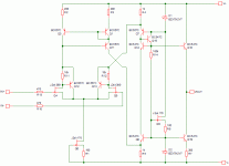
lineup said:High Fidelity Performance Op-Amp.
No need to make too complicated
when such good results with fairly simple 3 stage circuit
Set up this amplifier design model
in your simulator
and you will see!
and make a few small killer OPamp devices of your own.
Version 1 of mine used 17mA current total
at +/-15 Volt DC
and tested for practically 0% THD distortion, in various loads and output voltages.
Fourier Analyse shows very nice even spectrum of harmonics.
Hi
This looks nice.
Original schematic misses 47pF comp cap.
In my opinion if you go discrete and symetric supply it is better to connect compensation cap to ground than to -V because of PSRR.
IC op-amps of course can't do this, because they do not have 'ground' input.
regards
Adam
I may be doing something wrong but the circuit in my modeler does not perform nearly as well.
DC component:-0.000853152
Harmonic Frequency Fourier Normalized Phase Normalized
Number [Hz] Component Component [degree] Phase [deg]
1 1.000e+03 1.953e-01 1.000e+00 180.00° 0.00°
2 2.000e+03 1.477e-05 7.562e-05 177.20° -2.79°
3 3.000e+03 2.183e-04 1.118e-03 -5.15° -185.15°
4 4.000e+03 2.177e-05 1.115e-04 -8.40° -188.40°
5 5.000e+03 1.392e-04 7.125e-04 171.93° -8.07°
6 6.000e+03 1.664e-05 8.518e-05 171.65° -8.34°
7 7.000e+03 5.301e-05 2.714e-04 -11.51° -191.51°
8 8.000e+03 2.814e-06 1.441e-05 -18.72° -198.72°
9 9.000e+03 1.688e-05 8.641e-05 -20.48° -200.48°
Total Harmonic Distortion: 0.136513%
But then it may just be me with my limited knowlede of how to set the right working points.
I shall never ask such questions again sorry
Feel free to ask questions aroound here always. Some of the most clever and knowledgable people around here such as Nelson Pass will answer the smallest question. It is more the personality of the particular person. Some will give you a pedantic lecture , some will help. Some will help anyone, some will adjust their amount of help depending on how much the other knows- that seems the intellegent way to me. Also some don't want to putin the work required to figure out the details of specific circuits- they'd rather speculate on ideas. Some truly feel that you will learn more by investigating yourself, but that assumes that you have the basics..
Usually , if you phrase it right, someone will eventually get interested in what you are interested in!
I have elaborated a little with this basic schematic.
Raised rails to 50 V inserted jfet cascodes and changed transistors to MPSA 42/92 for the output stages.
Then I have added a lateral mosfet output stage, biased with a resistor in the current output stage.
This forms a very capable power amplifier. With some nice distortion figures.
Schematic added
Michael
Attachments
Here is some simulation data at 30 w output.
I have increased the current through the Singleended driver set to 12 mA.
Distorion may not be extremely low but the nature seems rather freindly.
feel free to coment.
Harmonic Frequency Fourier Normalized Phase Normalized
Number [Hz] Component Component [degree] Phase [deg]
1 1.000e+03 2.294e+01 1.000e+00 179.92° 0.00°
2 2.000e+03 1.210e-03 5.277e-05 89.90° -90.02°
3 3.000e+03 2.396e-04 1.045e-05 -178.16° -358.08°
4 4.000e+03 1.576e-05 6.869e-07 -10.75° -190.67°
5 5.000e+03 1.950e-05 8.502e-07 96.51° -83.41°
6 6.000e+03 4.610e-06 2.010e-07 167.17° -12.75°
7 7.000e+03 3.379e-06 1.473e-07 -86.62° -266.54°
8 8.000e+03 2.319e-06 1.011e-07 145.19° -34.73°
9 9.000e+03 2.149e-06 9.371e-08 -161.07° -340.99°
Total Harmonic Distortion: 0.005381%
rms_output_voltage: RMS(v(out))=16.2189 FROM 0 TO 0.099
rms_output_power: rms_output_current*rms_output_voltage=31.3664
Attachments
Hi,
sorry for not reading the entire thread, but I got inspired by the simple design i the first post, and I had to complicate matters a little. Here is what I come up with. I added at couple of BJTs to the FETs in the input, that increased the gain quite significantly. Then I made a discrete Darlington-stage in the output. I have not tried to optimise things at all, though the circuit might need some compensation. Open-loop gain is just above 110 dB, open loop bandwidth is just above 10KHz. I didf a FFT-simulation for unity-gain, 1V into 1K ohm in SIMetrixIntro without noise (its free but some what limited). The 2nd harmonic is the most «significant» distortion component at about – 130 dBV ... nothing much to speak about.
regards
KJ
Attachments
I have made some changes to the power amplifer i posted earlier.
The changes are BJT instead of fets for input cascodes. and more resilient driver transistors. I have for prototypes BD139 but i get the superior simulation results useing 2SC4793. Best with app 40 mA Trrough Driver stage. Small signal distortion is extremly low with 10V out. On FFT only 2. order is wisible.
This is now ready for prototyping.
DC component:-0.112709
Harmonic Frequency Fourier Normalized Phase Normalized
Number [Hz] Component Component [degree] Phase [deg]
1 1.000e+03 2.295e+00 1.000e+00 180.00° 0.00°
2 2.000e+03 5.205e-06 2.267e-06 140.81° -39.19°
3 3.000e+03 1.704e-07 7.421e-08 -153.64° -333.64°
4 4.000e+03 1.149e-09 5.005e-10 -4.84° -184.84°
5 5.000e+03 3.922e-10 1.709e-10 -14.82° -194.81°
6 6.000e+03 3.703e-10 1.613e-10 -43.16° -223.15°
7 7.000e+03 2.492e-10 1.086e-10 73.55° -106.45°
8 8.000e+03 3.592e-10 1.565e-10 57.95° -122.05°
9 9.000e+03 3.769e-10 1.642e-10 -11.49° -191.49°
Total Harmonic Distortion: 0.000227%
Hi lineup & KJ42 ,
I've followed your designs and made some changes from my
ULTIMA-PRE headphone-amp, using diamond output buffer.
See attachment:
If this work, then I'll add my new thermaltrack Power DB
http://www.diyaudio.com/forums/showthread.php?s=&threadid=96662
to become a 50W non-global NFB power amp.
I've followed your designs and made some changes from my
ULTIMA-PRE headphone-amp, using diamond output buffer.
See attachment:
If this work, then I'll add my new thermaltrack Power DB
http://www.diyaudio.com/forums/showthread.php?s=&threadid=96662
to become a 50W non-global NFB power amp.
Attachments
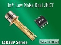
LSK389 Ultra Low Noise Dual JFET
mtlin12
my diy brother from eastern part of our world
Thank you very much,
because
was from your webpages
I first found out about Linear Systems Dual Monolithic ultra low noise JFET lines
1 nV and 3nV ... etc. etc.
you know, such like ... LSK389, LSK170, LS840, LS843
( they also have Hyper Modern SMT: DMOS small MOSFETs - with Great Data )
Most LS new dual JFET has got <20mV match by Vgs
They provide EXCELLENT Download Support of Spice Models in ZIP files
... and these Models work perfectly in My MultiSim. Those JFETs are only to add to my Library.
I use MultiSim -- Tools -> Component Wizard -- to add any new Spice Model
Thanks, mtlin12
for your shown interest in my works & amplifier circuits.
I know my circuits are not bad .... (some want them to be bad).
Actually Lineup circuits,
they are ... among the best ... at least in this place
... in My Own HUMBLE opinion
Regards in Audio
lineup
Lineup Audio Labs
.......................................................................................
References.
.......................................................................................
Attachment:
Image shows LSK389 dual jfet
Links:
mtlin12 - amplifier example!
http://wiki.diyzone.net/ULTIMA-PRE_PROTOTYPE_TEST_PICTURES
Linear Systems Download, Datasheets & Spice Models:
http://www.linearsystems.com/downloads.html
mtlin12 said:Hi lineup & KJ42 ,
I've followed your designs and made some changes from my
ULTIMA-PRE headphone-amp, using diamond output buffer.
See attachment:
mtlin12
my diy brother from eastern part of our world
Thank you very much,
because
was from your webpages
I first found out about Linear Systems Dual Monolithic ultra low noise JFET lines
1 nV and 3nV ... etc. etc.
you know, such like ... LSK389, LSK170, LS840, LS843
( they also have Hyper Modern SMT: DMOS small MOSFETs - with Great Data )
Most LS new dual JFET has got <20mV match by Vgs
They provide EXCELLENT
Download Support of Spice Models in ZIP files... and these Models work perfectly in My MultiSim. Those JFETs are only to add to my Library.
I use MultiSim -- Tools -> Component Wizard -- to add any new Spice Model
Thanks, mtlin12
for your shown interest in my works & amplifier circuits.
I know my circuits are not bad .... (some want them to be bad).
Actually Lineup circuits,
they are ... among the best ... at least in this place
... in My Own HUMBLE opinion
Regards in Audio
lineup
Lineup Audio Labs
.......................................................................................
References.
.......................................................................................
Attachment:
Image shows LSK389 dual jfet
Links:
mtlin12 - amplifier example!
http://wiki.diyzone.net/ULTIMA-PRE_PROTOTYPE_TEST_PICTURES
Linear Systems Download, Datasheets & Spice Models:
http://www.linearsystems.com/downloads.html
Attachments
mtlin12 said:Hi lineup & KJ42,
I've followed your designs and made some changes from my
ULTIMA-PRE headphone-amp, using diamond output buffer.
See attachment:
If this work, then I'll add my new thermaltrack Power DB
http://www.diyaudio.com/forums/showthread.php?s=&threadid=96662
to become a 50W non-global NFB power amp.
Very nice, mtlin12
Yes, this was my idea with my original more Principal Simplified Diagram.
To be some thing to start with.
And so we can adjust and modify my idea for our own circuits.
Most Diy amplifiers have one special purpose:
To take some special input source and to output the amplified signal into some specific existing Load Device.
So we make one custom circuit for our own specific needs.
mtlin12,
I attach your modificated, and sure Better! circuit. As an image.
(for original PDF, see mtlin12 post above)
Audio Regards
Hifi Amplifiers - by Lineup
Attachments
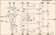
I like the CFP in the input.Hi,
sorry for not reading the entire thread, but I got inspired by the simple design i the first post, and I had to complicate matters a little. Here is what I come up with. I added at couple of BJTs to the FETs in the input, that increased the gain quite significantly. Then I made a discrete Darlington-stage in the output. I have not tried to optimise things at all, though the circuit might need some compensation. Open-loop gain is just above 110 dB, open loop bandwidth is just above 10KHz. I didf a FFT-simulation for unity-gain, 1V into 1K ohm in SIMetrixIntro without noise (its free but some what limited). The 2nd harmonic is the most «significant» distortion component at about – 130 dBV ... nothing much to speak about.
regards
KJ
Sure is that my circuit needs more gain. So, it will be less distortion.
Also there is the question of how to compensate ...
- Home
- Amplifiers
- Solid State
- New JFET Hifi Op-Amp release!