Rodolfo wrote:
Please tell me if we agree on this. Suppose we have a unity gain block with 1MHz bandwidth. We enclose this block in a PFB loop and boost its gain from unity to 40dB (x100). The bandwidth of this synthetic 40dB gain block will only be 10kHz.
Just as NFB reduces gain and extends bandwidth, PFB increaes gain at the expense of bandwidth. Similarly, any distortion of the original unity gain block will be increased by 40dB.
Yes.then summing node bandwidth should be orders of magnitude larger than working bandwidth for this scheme to work
Please tell me if we agree on this. Suppose we have a unity gain block with 1MHz bandwidth. We enclose this block in a PFB loop and boost its gain from unity to 40dB (x100). The bandwidth of this synthetic 40dB gain block will only be 10kHz.
Just as NFB reduces gain and extends bandwidth, PFB increaes gain at the expense of bandwidth. Similarly, any distortion of the original unity gain block will be increased by 40dB.
traderbam said:.....
Just as NFB reduces gain and extends bandwidth, PFB increaes gain at the expense of bandwidth. Similarly, any distortion of the original unity gain block will be increased by 40dB.
Brian, it is not surprising you are looking in the wrong direction, for you have steadfastly negated EC as an interesting opportunity through your reductionist PF-within-NF approach.
Looking in the right direction means considering a summing node with an unity gain bandwidth of 10MHz to 50 MHz as it is readily available off the shelf.
But then that is not even the usefull approach - i.e. off the shelf high performance OpAmps - the usefull approach is to design a slightly over unity gain differential amplifier providing say better than 140 dB signal to spurious products, over 20MHz 3dB corner frequency, and capable of driving the output stage (it helps if this output stage has moderate gain, say 6 dB for example to tame swing requirements).
Now a global EC amplifier built around this gizmo is a different kind of beast altoghether - if you allow me.
Rodolfo
PS And if one wants to design the ultimate subwoofer, then it makes sense to throw in a DSP working leisurely a 44 KHz as summing node.
Rodolfo,
I have never said EC is not an interesting approach. I am interested. I asked a simple question because I would like to know whether my understanding of how regenerative loops affect things. To a first approximation, is this diagram right?
Brian
I have never said EC is not an interesting approach. I am interested. I asked a simple question because I would like to know whether my understanding of how regenerative loops affect things. To a first approximation, is this diagram right?
Brian
Attachments

PB2 said:...................
There is a case of NIH going on here in my opinion:
http://en.wikipedia.org/wiki/Not_Invented_Here
Pete B.
 So, guys exploring different kinds of view are suffering from NIH? :bs:
Cheers, Edmond.
traderbam said:... To a first approximation, is this diagram right?
Brian
Eyeballing it looks good, and I trust you made the correct numbers. The 100x factor shows up wherever it is expected to be.
Now the devil is in the details as Bob insists, translated here where numbers fall, and there are a couple of things to note.
First, a 50 dB signal to distortion figure at unity gain is not fair, probably several in the forum that know better can come out with much higher performance.
Second, the summing node with positive feedback loop closed needs not 2MHz bandwidth, remember this bandwidth is equivalent with what in regular NF is OL bandwidth, that is, one should like to have it constant up to the upper working frequency limit which in this case is about 20KHz. In fact we accept it to roll off to less than DC OL gain at the upper working range.
One could be tempted at first to implement this node around a high performance OpAmp - I did it at first - until realizing that this way one may as well dispose off the EC scheme since it turns out just the same as leaving the OpAmp with no inner NFB, that is, to close a conventional feedback loop including the output stage.
The challenge then is, as I repeatedly stated, to desing a natively highly linear and wideband slightly over unity gain differential amplifier for summing node duty.
Rodolfo
Rodolfo,
Just to simplify things for the wider audience. The reason you need to find a very linear, wide-band device for the summer is because these qualities are traded-off against gain, approximately proportionately.
Am I being fair when I suggest that the decision the designer faces as to whether to use this cunning method to generate forward gain as opposed to using a conventional gain device, neglecting some circuit conveniences for the moment, is whether a unity (or close) gain device can be made/obtained that is better even when its performance is eroded in proportion to the required forward gain?
That was a long sentence. Can you show that there is something special about unity-gain differential amps in terms of bandwidth and distortion and output impedance that makes a synthetic gain block better in a practical circuit?
If so, then that is very interesting.
This I have a problem with. But let me park it for now.Second, the summing node with positive feedback loop closed needs not 2MHz bandwidth, remember this bandwidth is equivalent with what in regular NF is OL bandwidth, that is, one should like to have it constant up to the upper working frequency limit which in this case is about 20KHz. In fact we accept it to roll off to less than DC OL gain at the upper working range.
traderbam said:... Can you show that there is something special about unity-gain differential amps in terms of bandwidth and distortion and output impedance that makes a synthetic gain block better in a practical circuit?
If so, then that is very interesting.
.....
Yes, you can do it digitally (the output impedance is not an issue with a properly designed output stage).
The catch is to get the required badwidth to trade off, and current technology limits in principle this approach to subwoofers.
This is the same kind of tradeoff we accept in GNF, we design much higher than required OL gain to trade off for correction.
With respect to the second sentence, recall a regular OL / CL gain vs. frequency diagram. The correction margin - the ratio of OL to CL gain - most often begins to roll off below 20 KHz under conventional OpAmp style designs.
Rodolfo
PS. Whether an analog summing block yielding a better than conventional overall performance can be built, I am not qualified to decide, but think it may be worth a try as stopgap until say 40 Msamples/s 24 bit DSP building blocks including A/D are available. Thereafter, it is history.
Rodolfo wrote:
Indeed, often below 1kHz. That's not my concern. But I'll save this for later. After Jan and I have settled the NFB measurement thing.With respect to the second sentence, recall a regular OL / CL gain vs. frequency diagram. The correction margin - the ratio of OL to CL gain - most often begins to roll off below 20 KHz under conventional OpAmp style designs.
Forgetting digital control systems for the moment, the crucial question as far as I am concerned is whether to use a synthetic block (a la HEC) to boost the OL gain of a unity gain follower output or whether to insert a normal gain block. In either case the gain has to be "conventional" in magnitude to maintain stability so the PFB capability of unlimited gain is not really a practical benefit.PS. Whether an analog summing block yielding a better than conventional overall performance can be built, I am not qualified to decide
traderbam said:..... the crucial question as far as I am concerned is whether to use a synthetic block (a la HEC) to boost the OL gain of a unity gain follower output or whether to insert a normal gain block. ....
Yes, this is the right question to ask and I am glad at long last we agree, and the reason I insisted, for I do not have the answer in the sense of a demonstrable superiority one way or the other.
Rodolfo
how about explaining this view of EC?
just as a visual "suggestion" I've drawn an op amp symbol outline around the EC block that seemed to accepted earlier as a fair model to explore EC:
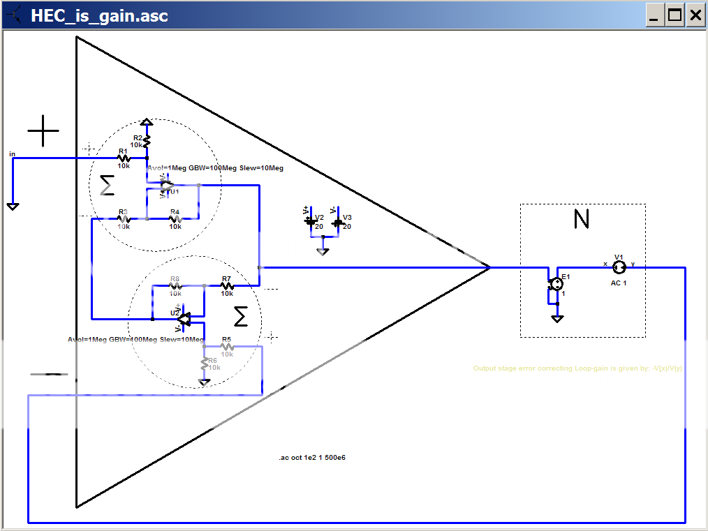
next I have tested the differential and common mode gains of the “visual aid” circuit:
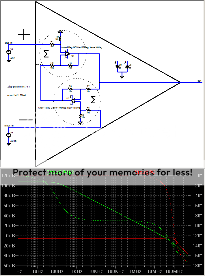
it appears to have a large differential gain, a low common mode gain and a tolerable 20K input impedance on each input, dominant pole compensation with some visible excess phase beyond unity gain - in short it is a fair approximation to a classic op amp
where exactly have any of my sims not demonstrated exactly what I claimed: that this circuit, which has been accepted as a model of EC, can be viewed as a high loop gain negative feedback around N?
just as a visual "suggestion" I've drawn an op amp symbol outline around the EC block that seemed to accepted earlier as a fair model to explore EC:
next I have tested the differential and common mode gains of the “visual aid” circuit:
it appears to have a large differential gain, a low common mode gain and a tolerable 20K input impedance on each input, dominant pole compensation with some visible excess phase beyond unity gain - in short it is a fair approximation to a classic op amp
where exactly have any of my sims not demonstrated exactly what I claimed: that this circuit, which has been accepted as a model of EC, can be viewed as a high loop gain negative feedback around N?
Attachments
jcx said:.....
where exactly have any of my sims not demonstrated exactly what I claimed: that this circuit, which has been accepted as a model of EC, can be viewed as a high loop gain negative feedback around N?
Kindly jcx, this is the same trap I fell a couple of years ago. If you implement the summing block with an OpAmp, it is useless to apply EC, it should - and does - give the same result as leaving the OpAmp simply open loop from the start, no surprises here.
Rodolfo
PS. More precisely, the DC gain changes with EC and is set by the error in the null adjustment. But what matters more, namely the gain slope and 0dB intercept are the same.
Actually doing the modeling/analysis with the real world limitations in place from the start is the means of avoiding the "trap"
the Spice universal op amp blocks are used very explicitly to model the real world circuit limitation of any circuit implementation of the EC circuit
Bob's circuit uses a few small signal transistors and resistors to build a "EC" amp that you are claiming could be "perfect" if only we could implement a more precise small constant gain in the summer
do you agree that the summer's small constant gain is deterimned by the local feedback resistors and the gain of the transistors? - please answer yes or no
do the transistors have limited open loop gain and at least single pole gain roll off?
jcx said:....
do you agree that the summer's small constant gain is deterimned by the local feedback resistors and the gain of the transistors? - please answer yes or no
do the transistors have limited open loop gain and at least single pole gain roll off?
First let me tell you I do not consider myself a dummy to be summoned to a yes or no answer. Please polish up.
Second and to the point, yes, as long as the summing node is made on an OpAmp paradigm - set gain with resistors, get as high as possible OL gain - then EC is useless. I said this several times in the past. This way with EC you erase what you made with local NFB and expose the bare OL transfer. By the way, you know the second OpAmp in the circuit shown is unnecessary.
Whether a different summing node design approach - striving for linearity and bandwidth instead of gain - in the end proves better, I don't know, perhaps someone does.
Rodolfo
Clever, jcx, very clever!
I don't doubt your analysis there as shown, only that it is far from how the circuit actually operates. The goal is not to obtain gain through the use of positive feedback, rather it is to derive the error signal and feed it back such that the distortion is nulled. You seem to miss the point of the output diff amp, it is not there to provide a sneak positive feedback path, which you force from it by opening the negative input, rather it is there to derive just the error term. And it does, when both inputs are driven.
You compare this to Armstrong's regeneration, where positive feedback is used to obtain more gain from low gain devices such as triodes. I think this is clever by the way. There was actually high gain in those circuits as a result of the regeneration. However, your analogy is flawed. The high regen gain in HEC is only seen when you open the negative input, which is not how the circuit works in normal operation.
It is interesting that in your test circuit for differential gain you have left out the output stage, the part of the design that is the reason for having the error correction circuitry in the first place. You have warped a design that had a diff amp to null out the signal and positive feedback, into a design with gain and only positive feedback. Yes the behavior is different and interesting.
I agree that your real world limitations are reasonable, and could represent a wide range of active devices.
Pete B.
Perhaps you can appreciate my frustration when you make what I consider an Orwellian "Black is White" statement and say I have fallen into a trap you carefully worked your way out of?
I am running out of ideas to bridge the communication gap - any implementation of "EC" is going to be limited by the real world components, in particular the finite gain and bandwidth of any known amplifying device in the loop
In my mind you are now saying your idealized view of "EC" is impossible within the currently known limits of electronic engineering? And that my point that the positive feedback does "bare" the gain of the active element in the EC circuit is central to the discussion of the faulty real world implementations of "EC" gain?
In that case we may have a point of agreement
But I thought at least in part we were discussing Bob’s implementation which does use finite gain and limited bandwith gain devices in the summer?
I’m sure I could abstract Bob’s circuit into a simplified Spice model – but I would include rx, Rpi Cpi, Ccb,Hoe... and still expect to see analogous limits to those illustrated in the above sim
I expect I could "improve" the depth of the EC distortion null - by increasing the local gain available in the summer circuit
I am running out of ideas to bridge the communication gap - any implementation of "EC" is going to be limited by the real world components, in particular the finite gain and bandwidth of any known amplifying device in the loop
ingrast said:
...Second and to the point, yes, as long as the summing node is made on an OpAmp paradigm - set gain with resistors, get as high as possible OL gain - then EC is useless. I said this several times in the past. This way with EC you erase what you made with local NFB and expose the bare OL transfer....
...Whether a different summing node design approach - striving for linearity and bandwidth instead of gain - in the end proves better, I don't know, perhaps someone does.
Rodolfo
In my mind you are now saying your idealized view of "EC" is impossible within the currently known limits of electronic engineering? And that my point that the positive feedback does "bare" the gain of the active element in the EC circuit is central to the discussion of the faulty real world implementations of "EC" gain?
In that case we may have a point of agreement
But I thought at least in part we were discussing Bob’s implementation which does use finite gain and limited bandwith gain devices in the summer?
I’m sure I could abstract Bob’s circuit into a simplified Spice model – but I would include rx, Rpi Cpi, Ccb,Hoe... and still expect to see analogous limits to those illustrated in the above sim
I expect I could "improve" the depth of the EC distortion null - by increasing the local gain available in the summer circuit
The use of the word "null" really bugs me. What do people mean when they say this? I was taught that "null" meant reduce to zero or eliminate. But this is not what happens in a real feedback circuit of any topology.
I wonder too whether it is the behaviour of those resistors in a HEC-type circuit that leads to the use of this word: whereby if you make them variable there is a value where the output error is minimized, changing the resistance either side of this point increases the distortion. Well, this is a side-effect of the nesting of FB loops. Just because there is a minimum point on the pot doesn't in any way imply that this point is or should be a zero distortion point in a real circuit.
Why not try to look at it in a completely different way? In a NFB loop with device generated loop gain, the designer adjusts the gain and the compensation through simulation and experiment to some optimum point and then fixes the values. In HEC its like this was all done and then a pot was installed afterwards so that the circuit can be "de-optimised" at will. Either direction the pot is turned the performance is decreased.
jcx said:.....In my mind you are now saying your idealized view of "EC" is impossible within the currently known limits of electronic engineering? And that my point that the positive feedback does "bare" the gain of the active element in the EC circuit is central to the discussion of the faulty real world implementations of "EC" gain?
In that case we may have a point of agreement
......
I expect I could "improve" the depth of the EC distortion null - by increasing the local gain available in the summer circuit
I do not say it is impossible within reasonable real world limits, but that EC using an OpAmp style summing block is the same as leaving its open loop gain alone. In this light the last sentence points to a hopeless goal. This is central for the case of looking for alternate implementations.
May be the communication gap is starting to narrow?
Rodolfo
The tone of your discussion here jcx is that your analysis, where you show high gain and suggest positive feedback and regeneration, is required to truly understand how EC works and to produce the error signal V(va).
However, this is not the case as is demostrated when I break the loop as I did here in this simulation. Note that there is no path for positive feedback, no regeneration and yet the error signal V(va) is the same as when the loop is closed:
http://www.diyaudio.com/forums/showthread.php?postid=1308152#post1308152
http://www.diyaudio.com/forums/showthread.php?postid=1308141#post1308141
There is no magic going on here. Your view is abstract and may be a valid alternate view, however it does not map back to the actual implementation and how it is intended to operate.
I'm going to try to drop this now, I really don't have time for more of this.
Pete B.
I don't understand the abstract part - I could build very nearly the circuit shown in the big triangle, pot it and hand it to someone with instructions measure the gains I simmed for this circuit
I could then ask them to connect it around N as illustrated and ask for an explanation of reduced distortion at the output of N
would a 3rd year EE student be tempted to ascribe the distortion reduction to the "apparent, abstract, theoretical" gain they had just measured? - how about their Professor?
- Home
- Amplifiers
- Solid State
- Bob Cordell Interview: Error Correction