Hi all,
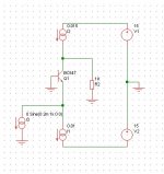
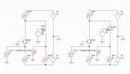
I'm currently working on an I/V converter for a current output DAC. Today I've been simulating (please don't bite me...) a few configurations, and the most basic one already shows some interesting results. (configuration is shown in the attached picture)
So we just have a common base stage, biased with perfect current sources.
I tried with PNP and NPN (you just have to miror everything)
The FFT showed a second harmonic H2 at around -80dB.
This is quite high for a stage with perfect biasing. Since the only thing not perfect here is the transistor, its non linearities already introduces that much distortion. It will of course increase further with real current sources.
Now, how to improve the linearity of a single pass element?
I tried 3 things I had in mind:
-using a darlington: distortion goes down to around -120dB!! whao, already a big improvement
-using a complementary feedback pair (CFP), H2 is now around -125dB
-with a super pair, it goes further down to -130dB
Those are the configurations I tried, because those are the ones I knew.
Now, does anyone have some advice about other things to try? Other linearization techniques or "super transistor" cells?
Attachments
An opamp would definitely suck at this (limited slew rate, falling OL gain at high frequencies, etc).
Basically what a DAC produces are square waves and opamps are not suited to processing square waves.
read this :
http://peufeu.free.fr/audio/iv.pdf
Basically what a DAC produces are square waves and opamps are not suited to processing square waves.
read this :
http://peufeu.free.fr/audio/iv.pdf
sawreyrw said:peufeu,
Why do you say this? It is clearly a function of frequency, and many op amp have GBWs greater than 50 MHZ. Furthermore, the discrete circuit will probably not be as fast as an IC solution.
Rick
Also, a slew rate is mostly a product of the 1'st transistor. We may assume that the whole OpAmp is a way to linearize it's characteristics.
Hi
You could use a Jfet as conversion element: this would give you perfect simulation results (no gate current/no error/Iin=Iout).
In the real world, second order effects would degrade the perfomances (the equivalent resistance of the source is relatively high), but you could find ways to mitigate this, as adding a BJT to make a composite, etc.
You could also add the Jfet as a cascode in your existing circuit to reduce non-linearities caused by the Early effect.
LV
Bricolo said:
Now, how to improve the linearity of a single pass element?
I tried 3 things I had in mind:
-using a darlington: distortion goes down to around -120dB!! whao, already a big improvement
-using a complementary feedback pair (CFP), H2 is now around -125dB
-with a super pair, it goes further down to -130dB
Those are the configurations I tried, because those are the ones I knew.
Now, does anyone have some advice about other things to try?
Other linearization techniques or "super transistor" cells?
You have already answered one thing we can do
to make better performance of stage
1. That is to use 2 transistors working together.
Basically 2nd ( 'output transistor' in CFP) transistor
takes the load of T1, which will operate in a very narrow part of its working point.
See D. Self basic simple research and tests
for some effects using single versus dual configurations
DESIGN WITH DISCRETE TRANSISTORS.
His findings regarding use of CFP is much the same as yours, Bricolo.
2. Another factor, to increse linearity,
is to reduce the load next stage will put onto this first stage.
This is not much more different or magical,
than a power amplfier
working into 8 Ohm will show better performance, than if working into 2 Ohms.
In a way,
reduced load is what happens in both these ways.
How can we improve, using this most obvious configuration:
CFP or darlington, with 2 (-3) transistors helping eachother?
Making up a super-transistor.
What say must be 2 JFET or 2 BJT or 2 MOSFET?
In CFP?
I have done some models using JFET + BJT foldback input stages
for high performance amplifiers.
(I am not talking about cascading.
Yet, I have never ever had to use any slow-down-cascade transistor for a helper in any amplifier.)
Let the JFET contribute what it does best
and Bipolar ( BC550C ) contribute its linearity by current
and if you need
add a small-signal MOSFET to this super-transistor stage
and let MOS contribute linearity at delta Vce ( VDS ) changes.
Within power transistors IGBT is such an attempt
to get best out of two transistor techniques.
Silicon and Metal Oxide Field Effect. BJT and MOSFET.
lineup
http://lineup.awardspace.com/
Elvee said:Hi
You could use a Jfet as conversion element: this would give you perfect simulation results (no gate current/no error/Iin=Iout).
In the real world, second order effects would degrade the perfomances (the equivalent resistance of the source is relatively high), but you could find ways to mitigate this, as adding a BJT to make a composite, etc.
You could also add the Jfet as a cascode in your existing circuit to reduce non-linearities caused by the Early effect.
LV
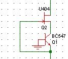
LV, is this what you called a composite?
It basicly is a BJT cascoded with a Jfet. I managed to get H2 at -100dB with this, but onl with low bias curents (the Jfet won't like much more than 5mA)
With a single Jfet, I can bring it down to -140dB, nice! But the input voltage varies quite a lot (0.5V) so the input impedance isn't low enough for a I/V converter.
A Jfet cascoded with a BJT on top is worse, -100 to -120dB
Attachments
No, I mean the effect of the non-zero input impedance seen at the source terminal: it means the ouput of the DAC will see a non-zero voltage, which will probably affect the linearity. As you seem to have modelled the DAC as an ideal current source, this effect will not appear in the simulation.Bricolo said:thanks, I'll give it a try.
by second order effects, do you mean that they are not taken into account in the Spice Jfet model?
LV
To answer your last message, by composite I mean a hybrid darlington, the first transistor being a FET for its low input current and the second a BJT for its high transconductance (and hence, its low emitter impedance).
I think you could use a PNP or NPN Bjt (connect them correctly however!), but in either case, it would be important to use a suitable B-E resistance, in order to set the fet operating current at some reasonnable value. I'd begin at around 1~2mA, say 470ohm.
LV
I think you could use a PNP or NPN Bjt (connect them correctly however!), but in either case, it would be important to use a suitable B-E resistance, in order to set the fet operating current at some reasonnable value. I'd begin at around 1~2mA, say 470ohm.
LV
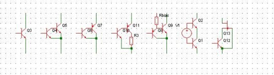
LV and Linesource, since I'm not exactly sure of what you have in mind, could you post a schematic to make it clear?
This is what I tried so far, from left to right
BJT, -80dB
Darlington, -120dB
CFP, -125dB
CFP with gain degeneration, THD increases whith the resistance
super-pair (baxendal's), -130dB
cascoded BJT, -80dB (same as a single BJT, maybe there's no improvement in cascoding a common base BJT)
BJT with a Jfet as cascode element, -110dB
Attachments
Bricolo said:please, that's not the topic here. there are plenty of topics and papers about "why opamps suck for i/v conversion"
The question was, if you tried it, and what are differences. I heard people say and write "suck" about everything, so I am just curious how it compares in reality...
- Status
- This old topic is closed. If you want to reopen this topic, contact a moderator using the "Report Post" button.
- Home
- Amplifiers
- Solid State
- Transistor linearization methods