Let's see now if I got it right. I used the PCB CAD file that's on that website, but with rectifiers and filter caps offboard so omitting that left section. I actually have CRC before the multiplier, and both the ground from the second pair of these caps, and the output ground, I wired to the two large holes in the middle of the multiplier half's star ground on the PCB drawing.
A few transistor shunt regulator on the front end may make an excellent regulator to complement the Krell PSRR. It could even have a lm317 or tl431 current reg upstream to reduce dissipation in the shunt and improve the rejection characteristics.Crowbar said:........If I were to use separate regulation for the rest of the amp (than the output stages), why not go all the way and use a good shunt regulator? Efficiency is really only an issue with the output stage anyway.......
Even a cascode reg might work (Walt Jung's recent paper posted on the Forum may help)
There are many options when we are dealing with <40mA @ 52Vdc.
They were the standard vanilla ones. The reason for low-ESR being undesirable is due to the 317's inductive behavior at higher frequencies. I've looked into that further and found this link: http://www.tnt-audio.com/clinica/regulators2_impedance1_e.html
it explains it rather nicely and was confirmed with my own measurements.
it explains it rather nicely and was confirmed with my own measurements.
Crowbar said:Let's see now if I got it right. I used the PCB CAD file that's on that website, but with rectifiers and filter caps offboard so omitting that left section. I actually have CRC before the multiplier, and both the ground from the second pair of these caps, and the output ground, I wired to the two large holes in the middle of the multiplier half's star ground on the PCB drawing.
A schematic would help.
the offboard main smoothing can have it's 0V returned direct to the audio ground.
the onboard smoothing has much reduced charging pulses, but they are still there.
I think your description is saying that the CRC 0v are connected to the local reg star ground. I would not do that. The first C should go to remote audio ground the second C could go to either the remote audio ground or to the reg OUTPUT. You should try to ensure that the MEASUREMENTS the regulator is making on the low current sense traces are uncontaminated by high current and/or high pulse power outputs.
PWatts said:They were the standard vanilla ones. The reason for low-ESR being undesirable is due to the 317's inductive behavior at higher frequencies. I've looked into that further and found this link: http://www.tnt-audio.com/clinica/regulators2_impedance1_e.html
it explains it rather nicely and was confirmed with my own measurements.
extracted from TNT
this is at odds with the National datasheet!But that supply line, and all the others, was controlled by an LM317 loaded with a 1uF low-Z ceramic cap nearby, and a dozen of 100nF caps distributed around the big chip. With about 2uF of low-ESR capacitance it was no wonder at all that this particular regulator was prone to oscillation. And the chip's current draw profile only exacerbated things. Trashing the ceramic cap in favour for a big ugly and cheap 100uF elcap entirely cured the problem and left the supply stable and of relatively low noise.
Who do we believe?
Crowbar,
go and look at the good & bad schematics on page one of that tnt link.
PWatts said:found this link
Pierre,
there's the option of communicating directly with Werner Ogiers, he's also a member of this club, aka Werner.
Born and living in Antwerp, his homepage=> HERE
(opposed to what Werner stated at the Duhh-HiFi forum, the inspiration for Werner's shunt reg did not come out of the van der Sluis sleeve. J van der Sluis knows squat diddly about designing circuits, the bloke just craves to get between the sheets with P. Walker and J. Hiraga types)
rjkdivin said:Linesource,
Your thumbnail link for the schematic is not functioning.
Robert
Attachments
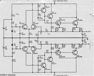
Regulator...
Hello chaps!
Very interesting this topic of ESR/Low ESR and adding a resistor to get some ESR! Wow! Fascinating.
I like the 317 circuit for its simplicity. Other than the ESR cap issue I guess it would do a good job.
I like the Linesource schematic as well though the component count is higher...still it would be mounted on a small PCB. Where is this circuit from? It looks like it could supply an entire power amp(a small one) ? To supply the Krell KSA100 driver board , I guess the 2SC2565/2SC1095's could be removed? The MJE182/172 should do the job ok?
Cheers,
Shawn.
This is not the first time there has been conflicting measurements (not counting opinions, but hard data), and isn't limited to just the electronic world.
I've experienced different behaviour with regulators from different manufacturers - even though they're the same design, performance often differs. This includes noise, distortion, transient effects and gain, albeit some of them very slightly and only picked up by the very best spectrum analyzers. It's a wild guess, but it may be possible that the National ones exhibit slightly less inductive response than the TI ones (and whichever brand Werner had used) and therefore not as much prone to the underdamped resonance. Maybe a good idea to take a number of unrelated 317's from TI, National, ST, Fairchild, ONSemi et al and perform consistency checks with those from the same manufacturer and then compare to the rest. My tests were only brief with a single TI 317 against an ST one.
I've experienced different behaviour with regulators from different manufacturers - even though they're the same design, performance often differs. This includes noise, distortion, transient effects and gain, albeit some of them very slightly and only picked up by the very best spectrum analyzers. It's a wild guess, but it may be possible that the National ones exhibit slightly less inductive response than the TI ones (and whichever brand Werner had used) and therefore not as much prone to the underdamped resonance. Maybe a good idea to take a number of unrelated 317's from TI, National, ST, Fairchild, ONSemi et al and perform consistency checks with those from the same manufacturer and then compare to the rest. My tests were only brief with a single TI 317 against an ST one.
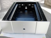
ATI chassis
Folks, I think this was discussed here but I'm not certain. Does the "big" ATI chassis attached have adequate cooling capacity to chill-out the KSA100?
Front plate: 482.60 w (19") X 165.10 h (6.5") ( 6mm thickness )
Body size : 355.60 w (14") X 162.56 h (6.4") X 596.90 d (23.5") ( 2 mm thickness )
Solid aluminum feet
Heat sink included
Switch Power on-off and knob included (Aluminum)
Thermal rating per side of the heatsink = 0.279 C/W
Cheers,
Shawn.
Attachments
I have a similar size amp to yours, only you have 4 sections of sinks down each side mine has 3. I use one of these for an aleph 2 monoblock which disipates 300 watts of heat, It has 8mm aluminium l;id and front plate, 4 mm base. It could easily dissipate 350 watts in our cool climate but wouldnot want to get hotter. I would say your case would be good for 400 to 450 Tops. A second one would be nice")
Chassis
Maybe Eboz from www.diyenclosures.com can make a custom chassis if there is enough interest.
And we, American, will save the shipping cost instead of buying chassis oversea like ATI or other.
Maybe Eboz from www.diyenclosures.com can make a custom chassis if there is enough interest.
And we, American, will save the shipping cost instead of buying chassis oversea like ATI or other.
Re: ATI chassis
is that for a monoblock or stereo?
Each channel has to dissipate Iq*Vrail*2. For a standard single channel biassed to 2.6A and running from +-52V that equates to 270W.
deltaTsink=270*0.279/derating factor. If DF=1 then one channel mounted on one side gives dT=75Cdeg. Add on ambient, add on Rth c-s, and you will have Tc~110degC.
Putting 270W through both sides gives Tc~72degC. Still a bit hot.
What would be the derating factor for 135W into these sinks when deltaT is 37.6Cdeg? Sinks are usually specified for 70 to 80Cdeg.
I think that the sinks are too small for a monoblock, they may also be too far apart and the long wiring could be a problem (I have this same problem to address).
I would aim for <=0.1C/W before derating for each monoblock dissipating 270W. If you change the rail voltage or the bias current, the operational dissipation has to be designed for.
Hi,TomWaits said:Does the "big" ATI chassis attached have adequate cooling capacity to chill-out the KSA100?
Front plate: 482.60 w (19") X 165.10 h (6.5") ( 6mm thickness )
Body size : 355.60 w (14") X 162.56 h (6.4") X 596.90 d (23.5") ( 2 mm thickness )
Solid aluminum feet
Heat sink included
Switch Power on-off and knob included (Aluminum)
Thermal rating per side of the heatsink = 0.279 C/W
is that for a monoblock or stereo?
Each channel has to dissipate Iq*Vrail*2. For a standard single channel biassed to 2.6A and running from +-52V that equates to 270W.
deltaTsink=270*0.279/derating factor. If DF=1 then one channel mounted on one side gives dT=75Cdeg. Add on ambient, add on Rth c-s, and you will have Tc~110degC.
Putting 270W through both sides gives Tc~72degC. Still a bit hot.
What would be the derating factor for 135W into these sinks when deltaT is 37.6Cdeg? Sinks are usually specified for 70 to 80Cdeg.
I think that the sinks are too small for a monoblock, they may also be too far apart and the long wiring could be a problem (I have this same problem to address).
I would aim for <=0.1C/W before derating for each monoblock dissipating 270W. If you change the rail voltage or the bias current, the operational dissipation has to be designed for.
This post states the two heatsinks of the ATI cases are rated at 0.075cw.
I don't kown what is the correct cw. Comparing the ATI-639M to the 4HE depth 400mm pessante dissipante from Hifi2000. They are both comparable in height, but the ATI is almost 20cm deeper. And if I recall correct the Hifi2000 has a cw of 0.22.
So the Hifi2000 is 20cm shorter, is looks otherwise comparable, but is more efficient in dissipating heat???
If the 0.075cw is correct, the case just becomes a whole lot more intesesting.
If it's any help: the ATI case is a close copy of the 1986 Jeff Rowland monaural Model 7 chassis, with the front plate design pinched from another big US audio boy.
The ATI also has 26 TO-3 mounting positions, just like the Model 7.
24 TO-3 output devices + 2 TO-3 driver devices on the M7
(or JRDG, or Rowland Research as the company was named back then)
The Model 7 run partly in Class A and was very modestly rated at 350 watts in 8 Ohms. (the actual power level was 450)
Some data and dimensions of the Model 7 should still be at Jeff's company site. (Jeff is turning 56 this year, just as big daddy P)
The ATI should handle 300 watts of dissipation with ease.
Don't believe it, go feel a model 7.
0.075 C/W should be on the spot.
- Home
- Amplifiers
- Solid State
- Krell KSA 100mkII Clone