jacco vermeulen said:Glad at least one here agrees, a JC-1 DC servo does wonders for a KSA50.
Look Ma, no Caps =>
Hi Jacco
Hmmmmm, interesting comment here though. Do you have any schematic for this DC-servo, or a link to point at?
Thanks in advance
Regards

I believe Goldmund uses the term capacitor smearing.
For me, the main types of cap coloration are Class AB output caps#, input lytics and electrolytic dc blockers in the nfb route, in that order.
Trouble with the general dc servo is that it removes but also adds, the worst type opamps add more than they contribute. Like TL07*/TL08* style dc servos, i've never used less than PMI OP** numbers.
imo, pretty obvious if compared to cases of different characteristic mechanisms on a single feedback loop from general neg/pos feedback classes in college.
In the dc servo prime time from the mid 80s upwards there were only a few fet input opamps, such as expensive AD types which in some cases were used for input stages of power amps.
It took Fred Dieckmann about a week to get the very basic reason through to my thick skull why fet input operational amplifier chips are the only ones suitable for active dc purposes.
A proper dc servo circuit setup can be found at the "other" (crumbling) forum. JC posted/confirmed enough about opamp type and opamp input filtering he uses in his amplifier designs.
The JC-1 schematic backs up Mr Curl's statements.(JC posted he now uses a BB 134 in the servo because of logistics)
My LSP system tends to go wobbly in the bottom, and my hearing is a dead fish in that region anyway, someone else has to comment on the low end effect of a dc servo.
To me, the effect of using a dc servo is like the difference of stepping up from a single rail output cap circuit to a push pull output stage.
(# interestingly, this does not apply to full Class A output stages, Zennies and such)
O&O.
Where exactly Jacco?jacco vermeulen said:................
A proper dc servo circuit setup can be found at the "other" (crumbling) forum. .............
were these discussions on the public Forum (here or DiyHiFi?) or private mails?It took Fred Dieckmann about a week to get the very basic reason through to my thick skull why fet input operational amplifier chips are the only ones suitable for active dc purposes.
Please link if possible.
AndrewT said:were these discussions on the public Forum (here or DiyHiFi?) or private mails?
Please link if possible.
DH
Regulator for Driver Board
Hi folks,
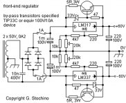
Just reading another thread & I stumbled into this regulator schematic. Thanks Jacco!
If a few bypass caps were dropped across the bipolar ones, would this not do a good job supplying the Krell KSA100 mkII boards?
It looks like it could be modified to fit many amplifiers for that matter? Or is it not up to snuff? If you don’t think such a circuit is up to the task, please post some other schematics or links so I can do a little more research.
Cheers,
Shawn.
Hi folks,
Just reading another thread & I stumbled into this regulator schematic. Thanks Jacco!
If a few bypass caps were dropped across the bipolar ones, would this not do a good job supplying the Krell KSA100 mkII boards?
It looks like it could be modified to fit many amplifiers for that matter? Or is it not up to snuff? If you don’t think such a circuit is up to the task, please post some other schematics or links so I can do a little more research.
Cheers,
Shawn.
Attachments
Re: Regulator for Driver Board
For a power amp, it's better to use a capacitance multiplier, as it allows you to maintain a minimum regulator dropout voltage without worrying about mains variation. I built Mr.Evil's design and it works good: http://mrevil.pwp.blueyonder.co.uk/amp/amp4/sub/psu2.shtmlTomWaits said:Just reading another thread & I stumbled into this regulator schematic.
Re: Regulator for Driver Board
+/- 80V input +/- 62V regulated output
Might be worth adapting for KMA super PCB.
TomWaits said:Hi folks,
Just reading another thread & I stumbled into this regulator schematic.
Shawn.
+/- 80V input +/- 62V regulated output
Might be worth adapting for KMA super PCB.
Attachments
Hi Tomwaits,
the 317/337 regulator will work.
It is specified with the bypass transistor to increase current capacity and dissipation. For a front end supplying less than 40mA these add ons are not required.
I would be very tempted to keep a 33V Zener from input to output (without a series resistor) to help the output caps charge up and reduce the differential across the reg during start-up.
The 317/337 performance is pretty mediocre and gets worse at higher audio frequencies and terrible above audio frequencies.
The PSRR of the Krell will have to work hard to make up for this deficiency. Very good output caps can help reduce noise and impedance being fed to your front end and the reg keeps the low frequency spectrum in check.
A Pass style non feedback regulator MAY perform better than 317/337.
A discrete feedback reg should perform better after sufficient development.
Re: Re: Regulator for Driver Board
has anyone tried a capacitance multiplier on JUST the drivers' supply. Even at 1.5Apk output the maximum dissipation will be just 5 to 6Wpk and tick over at about 300mW (could a FET be used as the active device irf540?).
Just had a look at mrevils circuit. I would never have realised it was a capacitance multiplier (well, activated version of). I see he uses a FET as the pass element.
NOTE, mrevil has returned the smoothing 0v separately to ground and NOT taken it to the reg output. This is the correct way to do it. One must strive to NOT contaminate the regulator 0v references with pulses coming into the smoothing.
Hi,Crowbar said:
For a power amp, it's better to use a capacitance multiplier, as it allows you to maintain a minimum regulator dropout voltage without worrying about mains variation. I built Mr.Evil's design and it works good: http://mrevil.pwp.blueyonder.co.uk/amp/amp4/sub/psu2.shtml
has anyone tried a capacitance multiplier on JUST the drivers' supply. Even at 1.5Apk output the maximum dissipation will be just 5 to 6Wpk and tick over at about 300mW (could a FET be used as the active device irf540?).
Just had a look at mrevils circuit. I would never have realised it was a capacitance multiplier (well, activated version of). I see he uses a FET as the pass element.
NOTE, mrevil has returned the smoothing 0v separately to ground and NOT taken it to the reg output. This is the correct way to do it. One must strive to NOT contaminate the regulator 0v references with pulses coming into the smoothing.
I've actually measured the LM317/337's to have better performance than many other IC regulators (not counting discrete ones) if properly implemented. Low-ESR caps on their outputs can actually lead to instability and it's more important to use a large output cap than a low-ESR one. At the load a nice one if parallelled with an electrolytic would help though.
The regulator I've been toying with is simply a high-power opamp with a stable reference (I used the 10V REF102) and gain. The OPA547 from TI is rated far higher than needed, and can supply a differential voltage of 60V. So you just need a high-voltage low-power opamp to perform the inverting function and run one 547 with only +Vcc and the other with -Vcc, configure the gain and there you have it. If you use the output of the positive regulator and run the inverting opamp and negative regulator at unity gain you even get the negative to track the positive but it's not necessary and I don't know of +-60V capable opamps.
I've tested one at 20W per 547 intended for a class-A preamp and it works excellent. Haven't used it in the actual circuit yet though but will soon. Of course since it's feedback-based it works best with the regulator located close to the load.
Since the highest-rated opamp I know allows +-45V rails it's only fit for the LTP which uses 39V, but if you can get a stable negative reference higher outputs are possible. For the drivers it may be necessary to go to the 548 or 549, the latter capable of 8A continuous and will handle the 3W or so used by the drivers without a sweat if you look at its SOA graph.
Unfortunately TI has recently stopped giving samples out of these excellent products and they're quite expensive.
That is a simplification. I think it's worth considering this issue in detail. This paper is useful, and the measurement can be done with anyone that has a signal generator (use your soundcard only up to when its filter kicks in though, which will be well below 48 kHz for a 96 kHz sound card):PWatts said:Low-ESR caps on their outputs can actually lead to instability and it's more important to use a large output cap than a low-ESR one.
http://www.calex.com/pdf/3power_impedance.pdf
Of course it's a simplification (after all 99% of what's said on diyaudio is if you look at AES and IEEE papers on the subjects), but just to illustrate that adding exotic super-low ESR caps at the output of a 317/337 without damping isn't NECESSARILY a good idea and can have an adverse effect in certain instances.
I know, I was kind of looking for an excuse to include that paper, as a damping network as described to flatten the impedance vs frequency is a great way to improve a regulated supply.
If I were to use separate regulation for the rest of the amp (than the output stages), why not go all the way and use a good shunt regulator? Efficiency is really only an issue with the output stage anyway.AndrewT said:capacitance multiplier on JUST the drivers' supply.
Can you rephrase that? I'm not sure I completely understood. Transformer/rectifier ground is connected to the multiplier output ground--both have the ground symbol. What other 0 V do you see there?mrevil has returned the smoothing 0v separately to ground and NOT taken it to the reg output.
Re: Regulator for Driver Board
They both show a ground symbol, indicating they are both connected somewhere else.
What is very important is that they are not connected from smoothing 0v direct to the nearest point on the schematic.
It is acceptable to take the smoothing 0v AND the regulator 0V using SEPARATE wires to a remote ground. This remote ground is often referred to as star ground, audio ground, main ground, etc. (but not chassis safety earth).
AndrewT said:......Just had a look at mrevils circuit. ............NOTE, mrevil has returned the smoothing 0v separately to ground and NOT taken it to the reg output. This is the correct way to do it. One must strive to NOT contaminate the regulator 0v references with pulses coming into the smoothing.
I will try again.Crowbar said:................Can you rephrase that? I'm not sure I completely understood. Transformer/rectifier ground is connected to the multiplier output ground--both have the ground symbol. What other 0 V do you see there?
They both show a ground symbol, indicating they are both connected somewhere else.
What is very important is that they are not connected from smoothing 0v direct to the nearest point on the schematic.
It is acceptable to take the smoothing 0v AND the regulator 0V using SEPARATE wires to a remote ground. This remote ground is often referred to as star ground, audio ground, main ground, etc. (but not chassis safety earth).
The datasheet for 317 & 337 show a low esr on both the input AND the output to ensure stability.PWatts said:I've actually measured the LM317/337's to have better performance than many other IC regulators (not counting discrete ones) if properly implemented. Low-ESR caps on their outputs can actually lead to instability and it's more important to use a large output cap than a low-ESR one. At the load a nice one if parallelled with an electrolytic would help though.
The instability you refer to is more usually associated with LDO regulators. I was not aware that the stability region diagrams afflicted the conventional 317/337 types (they are NOT shown in the National datasheets).
I read very recently that some 317s are available as low drop out versions and that these can fall into the normal LDO stability problems and low ESR aggravates this.
Can you confirm which types of 317/337 you are specifically referring to?
Read National.com, lm317, page 8, external capacitors. It even warns that some ceramics have a capacitance decrease at 500kHz and that this failing is overcome by swamping the effect by using lower impedance caps (1uF solid tantalum - but not at 60Vdc) on the output. (this is not a failing of the reg, it is the ceramic failing National are giving the solution for). The fact that National even mention ceramics on the output implies they are approving the use of ceramics at this location.
- Home
- Amplifiers
- Solid State
- Krell KSA 100mkII Clone