Yesperanders said:Good luck but I have serious doubts that you will be able to "kill" a Gainclone. Are you aware of the competition?

We already made the comparison...
rick57 said:We already made the comparison...
... and the differences were?
More tight and real bass, more clear and natural mid and high frequencies, more "air" and 3D...
widowmaker said:
More tight and real bass, more clear and natural mid and high frequencies, more "air" and 3D...
sounds like words from ''audiophile'' cable posts.
well i suppose the competition is being grossly underestimated here.
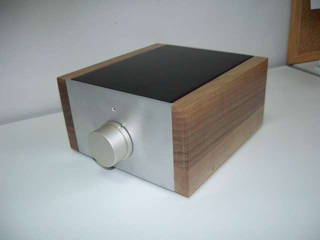
the gainclone looks better on your pictures
i don't like the gainclone sound very much anyway,call me crazy but i prefer the sound of class A amplifiers like the DOZ (Death of zen, looks like there is lots of blood in the Audio amplifiers world ) or good digital amps like the 41hz or autocostruire, or even better UCD modules, when lots of power is needed...
but lets talk about what is so good in your amp, i'm always looking after building new amps, but i'm poor.
the bgaudio.org site looks wonderfull anyway ! it's a shame i dont understand a thing !
i don't like the gainclone sound very much anyway,call me crazy but i prefer the sound of class A amplifiers like the DOZ (Death of zen, looks like there is lots of blood in the Audio amplifiers world
) or good digital amps like the 41hz or autocostruire, or even better UCD modules, when lots of power is needed...but lets talk about what is so good in your amp, i'm always looking after building new amps, but i'm poor.
the bgaudio.org site looks wonderfull anyway ! it's a shame i dont understand a thing !
sagarverma said:
sounds like words from ''audiophile'' cable posts.
well i suppose the competition is being grossly underestimated here.
well if you compare that to the words of gainclones lovers (" less congestionned mids"
) it's not so different, i suppose it depends on wich side you areHi, Darkfenriz,
If this is better then.....WOW
Hi, Widowmaker,
Is it possible to make your DOGC with higher voltage, say +/-50V? Cascoding the differential Jfet or use high voltage bipolars for differential?
I don't understand this. Better or worse than error correction? I feel that error correction is already a big help for low biased classABThe output stage is more 'transconductance' than error correction.
If this is better then.....WOWHi, Widowmaker,
Is it possible to make your DOGC with higher voltage, say +/-50V? Cascoding the differential Jfet or use high voltage bipolars for differential?
Hi, Widowmaker,
I see the important part in your DOGC is the 47ohm resistor.
Sometime ago, I proposed similiar idea but it is said to be ordinary CFP
http://www.diyaudio.com/forums/showthread.php?s=&threadid=62223&highlight=
In my idea, R5 works like your 47ohm, the difference is my idea works as "current source" final trans are common emitors, while in yours, the final transistors are emitor followers.
- Status
- This old topic is closed. If you want to reopen this topic, contact a moderator using the "Report Post" button.
- Home
- Amplifiers
- Solid State
- Death of Gain Clone