Barry blue, all i know is that we have to use
800 by 600 pixel images, so you will need some image program to resize your images.
I could see that exist someway to put bigger images, with better resolution, but i do not know the way to do that...but could see some images with more than 2000 pixels.
The limit is 100K, but could see some with bigger size.
Also i perceived that you can have 801 by 599, as the multiplication result is lower than 800 multiplied by 600 = 48000, but there are some limits related that.
As informed in the line "attach file", maximum size 102400 bytes, and valid image file extensions; gif, jpg, png,txt,zip,jpeg,pdf.
The smaller, as i could perceive, may be gif, but the more used images, a more standard image format is jpg or jpeg.
The best quality is pdf, from Adobe, but you will need some Adobe image converter, as normal Adobe program do not convert images to its format, only open images to watch and print... there are texts formats to Word program and to Word Pad.
The program i suggest to image, is the ACDSee, where you can correct focus, exposition, insert effects, reduce or increase colors, include or exclude colors, insert texts, resize and all kind of need you have related images.
Every image you have in the computer screen, can be captured pressing capslock and Print screen button...this will copy the image...so you open your paint program and click in paste...the image will appear, you can include texts, drawn into image and save it.... after that can open an image program, alike ACDSee, or Paint Pro and many others, and resize to 800 x 600, or even producing Avatar, that is 75 by 75 bytes images,better made when we use high contrast and high details...using image enhancing in image treatment programs.
regards,
Carlos
Attachments

Well barry, i have some old fully functional Demo, with timer.
...because or International rules and laws..related copyrigth and etceteras...i have some instructions to you related the place to upload.
nanabrother@yahoo.com
regards,
Carlos
...because or International rules and laws..related copyrigth and etceteras...i have some instructions to you related the place to upload.
nanabrother@yahoo.com
regards,
Carlos
GEM Schematic and Layout
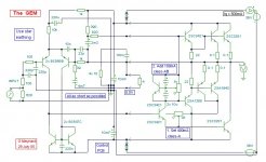
Please see the GEM schematic and layout below.
I have included in the schematic a basic bridge and capacitor circuit so that the PA can be a complete module if required. At this stage it is at draft level and some values are temporary (i.e snubbers).
The layout is still rather basic but should be correct to the schematic. There are three links which should show on the images.
One we have understood everyones preferences and experiences I will provide a final bill of materials if anyone is interested.
Constructive critism always welcome but rarely enjoyed.....")
Have fun
Please see the GEM schematic and layout below.
I have included in the schematic a basic bridge and capacitor circuit so that the PA can be a complete module if required. At this stage it is at draft level and some values are temporary (i.e snubbers).
The layout is still rather basic but should be correct to the schematic. There are three links which should show on the images.
One we have understood everyones preferences and experiences I will provide a final bill of materials if anyone is interested.
Constructive critism always welcome but rarely enjoyed.....
Have fun
Attachments

Hi Barry,
Excellent work.
I don't have the original schematics in front of me at the moment but I think there is a resistor missing between to lower driver emitter and output.
I noticed you added the Cdom to keep Carlos happy. and a resistor between signal and power ground.
Excellent work.
I don't have the original schematics in front of me at the moment but I think there is a resistor missing between to lower driver emitter and output.
I noticed you added the Cdom to keep Carlos happy.
and a resistor between signal and power ground.Was good idea to prevent the need of a Cdom
As sometimes it can be needed.
I congratulate you by the beautifull work you have done.
I wish you not need the capacitor, this way, certainly you will have the maximum possible quality of this very good amplifier.
regards,
Carlos
As sometimes it can be needed.
I congratulate you by the beautifull work you have done.
I wish you not need the capacitor, this way, certainly you will have the maximum possible quality of this very good amplifier.
regards,
Carlos
Thanks for the fast feedback
Sunrise, Greg and Mike,
Thank you for your fast feedback..much appreciated.
Sunrise : I will look at the default colours and try and change them. As for more groundplane I must admit to being torn on that. I used to think the more copper the better but now consider that it can create as many problems as it solves.....?
Greg, which resisitor on Graham's original schematic have I missed?
Brian, C13 seems to be the same as Graham's schematic...however it is late and my eyes do not work as well as they used too!
Carlos, thank you for the kind words. It seemed prudent to add the questionable capacitor
Hi Barry,
I have just studied you pcb layout and note that you are not using a star earth.
This is a common ground close to input to which all earthy connections should join to.
I have particular concern that the input filter capacitors are at the end of a long track.
The entire input circuit with capacitors could develop rf potential wrt the rest of the circuit.
(Yes sunrise, more grounding needed and should be centered on input area.)
I think the C.dom option is a good idea.
There could be the option of another capacitor to ground from input, as already used by our tutor, Carlos, to filter computer generated noise with direct connection, though I suppose that could also be part of the computer lead.
I always fit two input sockets in parallel per channel. May be used either for looping amplifiers, or for being able to plug in a terminating C or R.
Late for me too, more tomorrow.
Cheers .......... Graham.
Hi Barry,
Personally I would keep the noisy rectifiers/psu/line coupled transformer wires away from the pcb.
You do not need snubbers at the fuses when there is a large C either side.
I can assure you that the flash of a blowing fuse with this circuit is wire melting incandescence, and not a spark. (I'm sure Carlos would agree.)
It is also possible that you could parallel a pair of resistor holes with each fuse for 22 ohm then 0.22 ohm resistor fitment to facilitate initial start up testing and biasing; prior to finalising with fuse fitment.
(How will you do this if the outputs devices are all pcb mounted - and - bolted to the heatsink?)
You have the VAS and driver transistors shown as TO92 and not TO126 size, yet I do not know of any TO92 devices that could do this job.
Also the Vbe multiplier should be mounted on the heatsink for thermal feedback.
My suggestion is that everything from the VAS base onwards is mounted and hard wired on the heatsink, with all wires coming to a 4x TO92 pcb.
This should have a substantial central star earth. (I have redrawn the circuit to illustrate my layout, though nothing is drawn out.)
Each rail fuse should first supply rail capacitors and then star out from this separately to components plus heatsink; ie. do not have output device current through track resistance generating a fractional voltage that will modulate supply to the input stage.
My biggest worry with your existing layout is that your input socket is incapable of grounding interference on the screen of the input cable wrt amplifier input.
If you wish to have output devices and drivers pcb mounted then split the circuit and use two pcbs with separation at the VAS base and the positive driver base.
I trust you now understand what is meant by 'star' earth/grounding.
Keep the class-A power device physically closest to the VAS, and keep the inputs 5cm/2" away from output wires/Zobel etc.
Cheers ........... Graham.
Attachments
Re: Thanks for the fast feedback
You are getting me paranoid now. Hope I'm not going darf.
Notice second 22 ohm resistor R10 in sketch.
barryblue said:Greg, which resisitor on Graham's original schematic have I missed?
You are getting me paranoid now. Hope I'm not going darf.
Notice second 22 ohm resistor R10 in sketch.
Attachments
Well Graham, you calling me tutor, let me really embarrassed.
In my intimate feelings, i am so small in knowledge compared with your that i thank you very much, because of that respect that i really do not deserve.
I am a constructor, and a transistor X - extra destroyer, and to me, polish your shoes can be more than i hope for.
You are great, also Hugh and Mike, and i have enormous respect to all of you...levelled with John lindsey Hood (JLH).
I will copy your message, to show my friends that some respect to me.... well, milacres use to happen.
regards,
Carlos
Attachments
Re: GEM
Oh boy - this is nice - I like this schematic very much - thank You for the time - this is beutiful
regards and keep up the good work - like carlos said just polishing if I can
to carlos - is this the box where You would put Your amp in ? Is so - are those heatsinks are enough?????
also - nice to see that You put them that way....
regards
barryblue said:Sunrise,
Please see the schematic below which I hope is easier to view.
Graham,
Thank you for your comments. I look forward to hearing more before I start ripping up the layout
Barry
Oh boy - this is nice - I like this schematic very much - thank You for the time - this is beutiful
regards and keep up the good work - like carlos said just polishing if I can
to carlos - is this the box where You would put Your amp in ? Is so - are those heatsinks are enough?????
also - nice to see that You put them that way....
regards
- Status
- This old topic is closed. If you want to reopen this topic, contact a moderator using the "Report Post" button.
- Home
- Amplifiers
- Solid State
- Incredible quality amplifier by Graham, prepare your ears for it