Hi.
I have a bit of older MF gear, and I've been looking for some extra power amps to complete the HT setup.
I picked up a P170 the other day, it must be '80's gear, but I can't find a production date on it, so I'm guessing. Anyway, I'm going to replace all the Electrolytic caps in it, and then see how it compares to my other P150 and decide if it will be front or rear...
There is some evidence of previous repair inside, It looks like one of the caps has let go at some time in the past - there's a burn on the circuitboard near one of the transistors, and one of the 100uf/63v caps doesn't match it's other brothers - it's a 100v job, and a different brand - photo attached.
Apart from the cap replacement, is there anything else I should be looking at? The amp runs ok, and sounds good on my test setup of old bits 'n pieces.
Should I be looking to up the spec to 105 degree caps? They're 85 degree in there at the moment.
Any history on the P170? Unlike my other P150, this has a rear heatsink, and it weighs a lot!
Thanks,
Michael
Attachments
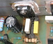
To me this is a bad repair. The overheated/burned PCB area should have been removed completely as it is highly conductive.
Replacing the caps with a 105°'s is not a bad idea if you plan to renew them.
/Hugo 🙂
Replacing the caps with a 105°'s is not a bad idea if you plan to renew them.
/Hugo 🙂
Netlist said:To me this is a bad repair. The overheated/burned PCB area should have been removed completely as it is highly conductive.
Replacing the caps with a 105°'s is not a bad idea if you plan to renew them.
/Hugo 🙂
Amen. I was quite shocked to find it too, I can tell you. I was also surprised that the other caps weren't replaced at the time, along with a couple of resistors that must have sufferred a lot of heat. I'll see what I can do about that while I have it in bits for the cap replacement - maybe cut it away and attach a bit of veroboard in it's place.
Michael
Are these suitable Caps?
The amp uses 63v/22,000uf, 63v/100uf, 50v/10uf, and 16v/220uf electros.
I have found these locally:
Farnell 22000uf (EPCOS B41560A8229M)
Farnell 100uf (NICHICON 4153406)
Farnell 220uf (Rubycon 16YXF220MY0811)
Farnell 10uf (Rubycon 50YXF10MY0511)
I really don't know much about Caps, are these all low-esr, and are they suitable replacements?
Thanks,
Michael
Michael
It's really hard to tell which caps would suit best where.
Other people here will be able to tell you more as I'm not a cap guru myself. And, without a schematic this could be a difficult task.
Anyway, the basic idea of choosing good quality caps is a good starting point and IMO you did.
/Hugo 🙂
It's really hard to tell which caps would suit best where.
Other people here will be able to tell you more as I'm not a cap guru myself. And, without a schematic this could be a difficult task.
Anyway, the basic idea of choosing good quality caps is a good starting point and IMO you did.
/Hugo 🙂
I had one of those for almost a decade a few years back.
If you want to improve things bigtime...just swap the existing op amps for the BB627.
You'll find that it gives you a completly new amp with a much, much cleaner sound. I found it pretty muddy and ruff or harsh as is. When I first got it i figured it was broken and got it exchanged for another unit but it was the same.
There is a horrible 317..something in there as original
/Michael
I remember repairing one of these once. The mosfets in your photographs aren't the originals, which are now obsolete. I guess that the charring on the pcb explains why the mosfets were replaced. As I recall MF used underrated resistors to drop the main power supply voltage down to +/-15V for the LM318(?) opamp. They get very hot and eventually scorch/char the pcb. They can usefully be replaced with constant current sources, as MF did in the P270/370. Be very careful if you have to desolder any parts from the pcb. It is a very cheap paxolin pcb with very thin copper tracks which lift off when you so much as look at them. I have no idea of whether the model I worked on was an early or late version so things might have improved since the one I had experience of.
Yeah, these were always fun to work on. That looks like a very "fast" repair, read poor. Remove the charred area. You can replace it with Epoxy glue and trim it down wit ha razor. That works for me in these situations. Drill new holes and connect point to point.
-Chris
-Chris
chalky said:I remember repairing one of these once. The mosfets in your photographs aren't the originals, which are now obsolete. I guess that the charring on the pcb explains why the mosfets were replaced. As I recall MF used underrated resistors to drop the main power supply voltage down to +/-15V for the LM318(?) opamp. They get very hot and eventually scorch/char the pcb. They can usefully be replaced with constant current sources, as MF did in the P270/370. Be very careful if you have to desolder any parts from the pcb. It is a very cheap paxolin pcb with very thin copper tracks which lift off when you so much as look at them. I have no idea of whether the model I worked on was an early or late version so things might have improved since the one I had experience of.
Thanks chalky, A 8, anatech and Netlist for the good info!
I can't see any evidence of overheating resistors, apart from the one near the burn which looks like it was caught in the crossfire 🙂 Is it likely that they have been replaced already, or that some other change was made to alleviate the problem? I have a photo of the whole interior if it would help, but it's about 1mb - I can upload it to my webspace if it would help or anyone is interested.
The opamp is indeed a 318 - labelled LM318 OP749 - I'll have a look for some BB627's for it - these are socketed, so can I just drop in the replacement with no other change?
I'll be careful with the soldering, thanks for the warning.
Michael
Hi maf_au,
I would definately replace all the electros near the heatsink/MOSFETS/power resistors or anything else that gets hot, with 105C types.
On replacing the 318 with the OPA627 (or even better OPA637 if it can handle the decomp BW), I would check for method of offset adjustment in the cct as it may utilize the chip offset pins which may be different and/or cause problems if it activates a non-active pin.
A schematic would clarify. Better safe than sorry.
Cheers,
Greg
amplifierguru said:Hi maf_au,
I would definately replace all the electros near the heatsink/MOSFETS/power resistors or anything else that gets hot, with 105C types.
On replacing the 318 with the OPA627 (or even better OPA637 if it can handle the decomp BW), I would check for method of offset adjustment in the cct as it may utilize the chip offset pins which may be different and/or cause problems if it activates a non-active pin.
A schematic would clarify. Better safe than sorry.
Cheers,
Greg
Hi Greg,
How would I get hold of a schematic? (sorry, newbie at this stuff) or are you saying I should draw one from the circuit board?
Given the age of the amp, I have ALL the electro caps down for replacement - tho only costly ones are the 4 22,000uf/63v.
Heh. By the time I have done the caps and opamps, I will have spent more on the amp than I paid for it! Once this is done, it will be the P150's turn. It's in the A1 chassis with the heatsink case - not looking forward to dealing with the heatsink goo and tight space there...
I've had the P150 since new, and it hasn't missed a beat. I bought it just after they were discontinued - must have been around 1990, but my memory for dates isn't so hot, it came with a preamp 3A, which has an active and passive output - always had a lot of noise in active, so I used passive, which was at least quiet. It doesn't get much use these days.
Michael
Hi.
Ok, I've searched, but can't find a schematic.
Hunted on my system and found a program called 'oregano' for capturing electronic circuit schematics, I'll have a go at it while I have it apart to replace the caps.
Is there someplace that collects schematics that I can upload it to when done for the next person to use?
Thanks,
Michael
Ideally you need to hunt down a schematic. However you could access the area of the board around the chip and check for pin connections to the cct from pins 1,5 I think it is to +Vs for the OPA627. LM318?
Your quest.
Cheers,
Greg
Your quest.
Cheers,
Greg
amplifierguru said:Ideally you need to hunt down a schematic. However you could access the area of the board around the chip and check for pin connections to the cct from pins 1,5 I think it is to +Vs for the OPA627. LM318?
Your quest.
Cheers,
Greg
Hi.
I hunted google and this site, but couldn't turn one up. That's why I was wondering if anyone is creating an archive of them.
They're LM318's - it was suggested some improvement might be had by swapping them for 627's, which I have coming with the caps, as I'm sure they will get used elsewhere if not on the P170... I think I've been infected with DIY..
I'll have a go at creating a full schematic of the amp, and I'll upload it here and send it to Mr Hennesy, maybe he'll archive it on his site...
Maybe on the weekend...
Michael
Hennesy should have the schematics, I think I sent it to him some time ago.
Regarding swapping the 318, I seem to remeber that there are no dc ofset adjustments only a freq-compensatio pins/curcuits/components that you need to disconnect. Other then that it should work as is. The 637 will probably make the amp go into oscillation.
Regarding swapping the 318, I seem to remeber that there are no dc ofset adjustments only a freq-compensatio pins/curcuits/components that you need to disconnect. Other then that it should work as is. The 637 will probably make the amp go into oscillation.
Ok, I have the schematics, thank you Mark and A 8 🙂
Here is what I see on pins 1 and 5 on the 318:
Pin1 via 3K3 and 2n2 to Pin5
So should I just hook them out and swap in the 627?
Regarding replacing the caps, especially the 22,000uf jobs on the PS:
How should I (safely) discharge them before working on them?
Is running the amp disconnected from the power for a while enough to discharge them, or should I ground the + terminal as well? Not wanting to get fried this week, and aware of the potential for stored current in these puppies...
At this stage, I'm going to replace caps, repair board and re-assemble. If everything behaves at that point, I'll swap the opamps.
Michael
Firstly, if you have any power resistors around say 5W'ers then work out from the supply voltage stored on the caps whether they would be in their ratings if placed across one C to ground i.e. P=VxV/R. Then just hold it on -the the other(s).
The RC on pins 1,5 sound like comp for the 318. I haven't used one for decades. Can you post the amp schema..
Cheers,
Greg
The RC on pins 1,5 sound like comp for the 318. I haven't used one for decades. Can you post the amp schema..
Cheers,
Greg
amplifierguru said:Firstly, if you have any power resistors around say 5W'ers then work out from the supply voltage stored on the caps whether they would be in their ratings if placed across one C to ground i.e. P=VxV/R. Then just hold it on -the the other(s).
The RC on pins 1,5 sound like comp for the 318. I haven't used one for decades. Can you post the amp schema..
Cheers,
Greg
Thanks for the reply!
Ok, bear with me, I'm new to this. I've got the bit about grounding the cap to earth via a power resistor, but calculating the load:
P=VxV/R
Am I on the right track here:
I'm thinking that V= the tranny output volts, R= the power resistor value ohms, so assuming I had a 5k/5w resistor, and the tranny was putting out 63v:
P=63 x 63/5000 = 0.79 (watts?)
So, my 5watt/5k resistor would be fine, and turning the eq around, I'd need a 793.8ohm/5w resistor or better?
I've asked A 8 if it's ok to post the schematic...
Thanks,
Michael
They are for comp so yes desolder them, there should also be a 5p Mica between output and pin 8, disconnect pin 8 and do the swap. You may want to keep it but connect the other end to the inverted opamp input. Cant remember what I did.
I think I also added filmcaps to the opamps powersupply.
I think I also added filmcaps to the opamps powersupply.
I just sent you a private message.
BTW my unit had the K1058/J162 mosfets in them and it worked great with the 627, your unit seems to have a lot of components replaced which theoretically can change how it behaves with new opamps. Be watchful of dc level on the output of the amp and current drain when you first power it up after placing the 627 in there.
BTW my unit had the K1058/J162 mosfets in them and it worked great with the 627, your unit seems to have a lot of components replaced which theoretically can change how it behaves with new opamps. Be watchful of dc level on the output of the amp and current drain when you first power it up after placing the 627 in there.
- Home
- Amplifiers
- Solid State
- Musical Fidelity P170 Power Amp