Yes maf_au you're on track. generally when I design an amplifier I include drain down resistors for the power supply. They only need bleed 5 mA or so .. so that by the time the lid is unscrewed they're as good as discharged.
A8 - you designed this unit? So the pins 1,5 and 8 can be relieved of components to implant a OPA627?
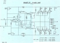
Sorry I don't know the design so without a schema.. I'm working blind.
Cheers,
greg
A8 - you designed this unit? So the pins 1,5 and 8 can be relieved of components to implant a OPA627?
Sorry I don't know the design so without a schema.. I'm working blind.
Cheers,
greg
amplifierguru said:Yes maf_au you're on track. generally when I design an amplifier I include drain down resistors for the power supply. They only need bleed 5 mA or so .. so that by the time the lid is unscrewed they're as good as discharged.
A8 - you designed this unit? So the pins 1,5 and 8 can be relieved of components to implant a OPA627?
Sorry I don't know the design so without a schema.. I'm working blind.
Cheers,
greg
Thanks.
Looks like the replacement caps aren't going to make it here today, I might spend some time on the weekend identifying and recording the differences between my amp and the schema, just in case there is something that shouldn't be...
Michael
You're doing well. If you can permanently fit 22k 1W resistors across all your PS C's that would ensure some safety. They won't degrade performance.
The components on pins 1,5,8 can safely be removed if you want to use a OPA627. The 3K3 at the input filter may be picking up excess hum and noise, depending on the layout. Replacing with 1K or a parallel equiv might be worthwhile.
I wouldn't use an OPA637 in this cct.
Good luck,
Greg
The components on pins 1,5,8 can safely be removed if you want to use a OPA627. The 3K3 at the input filter may be picking up excess hum and noise, depending on the layout. Replacing with 1K or a parallel equiv might be worthwhile.
I wouldn't use an OPA637 in this cct.
Good luck,
Greg
Caps
Well, the caps have all arrived. Danged if I could get any of the well-regarded brands and types locally in Australia, but these should get me going, maybe I'll tweak it later when I work out how to get those brands here...
Anyway, in place of the 2 x 220uf/16v I have been supplied with 330uf/16v. I cannot place these values on the schematic, I think they are in place of the 100uf caps shown bridging to ground on the incoming power + and - rails.
Should the 330uf caps be ok, or should I try and get 220uf?
No idea about how tolerant the circuit is to changes like this, the supplier didn't even mention the switch, so it's either commonplace, or an error.
Michael
Hi maf-au,
The 330uF are substituted for the 220uF in the input leg of the feedback loop. If they fit they'll be OK though you may have a slightly different thump at on/off than before.
One weakness of this type of driver stage design is that as the driver transistors get warmer for whatever reason, the design tends to deflect more current to the stage and turning on the output harder. It's only minor but a point. I have a similar design here I've been assessing. So instead of the bias having a neutral or -ve tempco, it's slightly +ve.
Good luck.
Greg
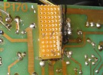
And here is the new piece inserted.
It's not pretty, but it should work ok, and it's a lot better than what was there before...
New caps are installed, just have to drill some holes for the MOSFET, line it up, do the point to point soldering with the other components effected by the burn, repair the pcb track I cut cutting out the damage.
Attachments
Ok, I think I'll quit while I'm ahead, it's nearly 1am here.
I'm worried about how to get the height of the MOSFET correct so that it lines up with the hole in the heatsink. Pity the case hasn't got a removable baseplate.
Edit: Just realised that I can remove the heatsink from the case and mount it to the PCB so that everything lines up, make my connections, disassemble, reassemble, enjoy...
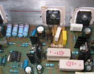
Next problem once the repairs are complete, and the amp is actually working again, is to replace the PS caps. The original ones are 40mm diameter, the new ones are 50mm. 4 of them won't fit between the toroids, so I'll have to have one running across in front of one of the toroids. They also won't fit the existing brackets...
Should I maintain an airgap between the PS Caps? I'll have to think about how to secure them.
Hmm. time for bed.
I'm worried about how to get the height of the MOSFET correct so that it lines up with the hole in the heatsink. Pity the case hasn't got a removable baseplate.
Edit: Just realised that I can remove the heatsink from the case and mount it to the PCB so that everything lines up, make my connections, disassemble, reassemble, enjoy...
Next problem once the repairs are complete, and the amp is actually working again, is to replace the PS caps. The original ones are 40mm diameter, the new ones are 50mm. 4 of them won't fit between the toroids, so I'll have to have one running across in front of one of the toroids. They also won't fit the existing brackets...
Should I maintain an airgap between the PS Caps? I'll have to think about how to secure them.
Hmm. time for bed.
And when it's back together
Can anyone detail what process I should do to check things are ok before applying power, then before hooking up speakers?
Should I power it up with no inputs and no speakers first? Should I put some load across the speaker terminals?
Assuming it doesn't explode when I first apply power, what should I be checking? (lol, apart from smoke)
I have a digital multimeter, will it help tell me if everything is ok? How do I test?
With a bit of luck, I'll have it back together after work tonight.
I've identified the components that link pins 1 and 5 on the LM318, and I think I can isolate them from the opamp without removing the circuit board again by using sidecutters. This has the added benefit of being able to easily reinsert them if things go awry with the 627's in place... Of course, I won't play with the 627's unless the amp powers up and plays normally with the 318's.
Any advice welcome, I'm a newbie at all this...
Michael
Cap support
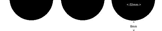
This is what I'm thinking:
A block of nylon 15-20mm thinck as per the image below.
I can attach it to the floor of the amp with tek screws from below, lay the caps on it and ziptie them on. Probably drill holes in the nylon to pass the zipties through.
Michael
This is what I'm thinking:
A block of nylon 15-20mm thinck as per the image below.
I can attach it to the floor of the amp with tek screws from below, lay the caps on it and ziptie them on. Probably drill holes in the nylon to pass the zipties through.
Michael
Attachments
It's back together, just checking for the millionth time, then it's powerup time...
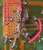
Topview. You can see the breadboard insertion, and the dots marking the cut points to detatch the components from the LM318 ready for the 627's
There's still a small amount of burnt board there. but it's not bad, and it's isolated. I didn't want to cut through the last remaining mosfet point...
Powerup in 15 minutes. If you notice something bad reply quick")
Topview. You can see the breadboard insertion, and the dots marking the cut points to detatch the components from the LM318 ready for the 627's
There's still a small amount of burnt board there. but it's not bad, and it's isolated. I didn't want to cut through the last remaining mosfet point...
Powerup in 15 minutes. If you notice something bad reply quick
Attachments
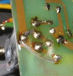
Bottom view.
I've checked and double checked this against the same circuit on the other channel, (it varies from the schematic because my amp has had it's mosfets replaced)
I'm no ace solderer, but I think the previous repairer was using a blowtorch! There is flux spatter all over the place, and he must have got solder at a discount - some of the powersupply connections are loaded with great gobs of solder...
Attachments
amplifierguru said:Hi Maf_au,
With little test gear, I'd put a 10R 1W across each channel speaker terminals, turn it on with no signal and see if they smoke. If not, measure DC across them. If <20mV try a small LF signal and see if you can measure some AC.
Cheers,
Greg
Ok, initial poweron is without smoke
Edit: found the millivolt range on the multimeter...
I have -0.3mv dc on left channel and 6.7mv dc on the right channel with the resistors in place.
Nothing is getting hot, the mosfets seem to be warm as per usual.
How do I create a 'small LF Signal' ?
Michael
I've powered it off and opened the case to inspect if anything is misbehaving. It was on for about 20 minutes, nothing hooked up, but with the resistors across the speaker terminals.
There's four blocky resistors - look like little cement blocks with axial connections - Power resistors? marked PW5 1K5 - anyway, they are quite hot. Everything else is cool to just warm.
Do those resistors normally run hot?
I'm off to bed. So far it looks like it's a good result. I'm thinking of hooking up some speakers in the morning, what do you reckon?
Michael
- Status
- This old topic is closed. If you want to reopen this topic, contact a moderator using the "Report Post" button.
- Home
- Amplifiers
- Solid State
- Musical Fidelity P170 Power Amp