Update
Well, I finally found out what the "problem" was with my Squeezebox SlimServer software not playing the LTSpice output file. The "problem" was a short between the headsets (figuratively speaking)") . Turned out I had inadvertently swapped the LTSpice WAV files, one of which was a one-for-one copy of the input, the other being the error voltage.
. Turned out I had inadvertently swapped the LTSpice WAV files, one of which was a one-for-one copy of the input, the other being the error voltage.
The error voltage file was nothing but silence. At least, I couldn't hear anything. So I was actually listening to the error voltage file, which was actually playing silently, when I thought I was experiencing playback errors when listening to the input.
So the result of listening to the error voltage via Squeezebox->Benchmark DAC->Sennheiser 580 headphones was complete silence. Even though a transient response shows glitches at the beginning of, say, a sine wave starting at t = 0, this is a result of the non-bandwidth-limited nature of such a signal. When a bandwidth-limited test signal is applied, it appears that the presence of the output inductor is inaudible - at least for this particular source material and simulated loudspeaker load.
Well, I finally found out what the "problem" was with my Squeezebox SlimServer software not playing the LTSpice output file. The "problem" was a short between the headsets (figuratively speaking)
. Turned out I had inadvertently swapped the LTSpice WAV files, one of which was a one-for-one copy of the input, the other being the error voltage. The error voltage file was nothing but silence. At least, I couldn't hear anything. So I was actually listening to the error voltage file, which was actually playing silently, when I thought I was experiencing playback errors when listening to the input.
So the result of listening to the error voltage via Squeezebox->Benchmark DAC->Sennheiser 580 headphones was complete silence. Even though a transient response shows glitches at the beginning of, say, a sine wave starting at t = 0, this is a result of the non-bandwidth-limited nature of such a signal. When a bandwidth-limited test signal is applied, it appears that the presence of the output inductor is inaudible - at least for this particular source material and simulated loudspeaker load.
Hahahaha Andy,
"The error voltage file was nothing but silence. At least, I couldn't hear anything. So I was actually listening to the error voltage file, which was actually playing silently, when I thought I was experiencing playback errors when listening to the input."
Maybe it'd be more audible with the music playing?
Cheers,
Greg
What's even funnier is that I didn't discover this until after I had written code to figure out the values of the missing byte counts in the LTSpice WAV file headers, and write out a new file with these numbers put back in. Turns out that the players seem to ignore these numbers anyway, and just read data until end of file is hit.
That's what writing software will do to you.
That's what writing software will do to you
.Hi Andy,
That calls for some beer therapy?
I remember, in about 1970, doing a huge integrated amp PCB layout on a light table with tapes and donuts using those SOT23 plug in small signal BJTs popular then, and after about a weeks work I was checking it over and discovered that ALL the transistors were mirror image pinout and the routing was ****.
I was gutted.
Cheers,
Greg
Re: The error voltage file was nothing but silence
It's beginning to look that way isn't it? Maybe a capacitive load would give some sound in the error voltage file. I'll try to think of some music with lots of transients and other high-frequency stuff also. I picked the Steely Dan selection because the recording quality is very good - not so much on whether or not it contains many transients.
Jorge said:Or could it be that just a small damped inductor doesn't matter?
It's beginning to look that way isn't it? Maybe a capacitive load would give some sound in the error voltage file. I'll try to think of some music with lots of transients and other high-frequency stuff also. I picked the Steely Dan selection because the recording quality is very good - not so much on whether or not it contains many transients.
Hi Andy,
A non-obvious oversight is still possible, or could it be that 16/44.1 has insufficient resolution to convert error waveform ?
Did you run a steady sinewave test ?
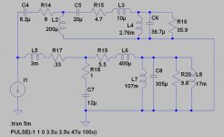
I have set up exactly the same as your Post#496 circuit in my simulator, and there is a notable 80mV error voltage, at minus 34 degrees, for 1V~10kHz steady sine input.
Any 10kHz music component could not fail to generate this -22dB differential error potential, and it should be resolvable.
Cheers ........ Graham
A non-obvious oversight is still possible, or could it be that 16/44.1 has insufficient resolution to convert error waveform ?
Did you run a steady sinewave test ?
I have set up exactly the same as your Post#496 circuit in my simulator, and there is a notable 80mV error voltage, at minus 34 degrees, for 1V~10kHz steady sine input.
Any 10kHz music component could not fail to generate this -22dB differential error potential, and it should be resolvable.
Cheers ........ Graham
With the lack of clarity of the diagrams it is impossible to comment.
BUT - and I hope this is not trouble. I have been familiar with Mr Hiraga's philosophies since about 1970, and his sometimes debatable views on feedback.
Let me be kind and just state, if this happens to be part of the debate. (I have joined recently and am unfamiliar with past post):
With negative feedback PROPERLY APPLIED it is certainly possible to design an amplifier with inaudible distortion under normal operation, meaning only low order harmonics. (Example: 2nd = 0.008%; 3rd = 0.006% and all higher buried in the noise at 0.001%) - this particular example for a 70W unit with 28 dB of negative feedback.) As a check, removing the feedback increases the harmonic components by the feedback factor, indicating that things behave as intended.
Power supply influence can certainly be critical and is indeed an often overlooked source of irritation. Somehow I would also be interested in the article results in readable form. (It bothers me that no Y-axis scale appears to be given, unless that was in the text.)
Sorry All!
. . . but my immediate previous post will make little sense at this point in the thread. I started off by intending it as part of the discussion of an article by Jean Hiraga, posted by Lumanauw as long a go as May 27, page 1 of this thread I think.
A wrong key was probably pressed, with a little help from Murphy. I apologise and hope interested parties can tie it back to where it was intended to be.
Thanks
Johan Potgieter said:Sorry All!
....and hope interested parties can tie it back to where it was intended to be.
Thanks
No need for apologies Johan, you are most welcome. Please take your time to pore the over 50 pages, you will probably find interesting stuff.
Rodolfo
Re: Re: The error voltage file was nothing but silence
Andy:
This thing made me recall something I posted by Nov/04 regarding null tests and analysis possibilites.
Guess next step is to record actual input and output for several amplifiers in stereo files and have a look.
Rodolfo
Andy:
This thing made me recall something I posted by Nov/04 regarding null tests and analysis possibilites.
Guess next step is to record actual input and output for several amplifiers in stereo files and have a look.
Rodolfo
Graham Maynard said:Did you run a steady sinewave test ?
I have set up exactly the same as your Post#496 circuit in my simulator, and there is a notable 80mV error voltage, at minus 34 degrees, for 1V~10kHz steady sine input.
Any 10kHz music component could not fail to generate this -22dB differential error potential, and it should be resolvable.
Yes, I did a sine wave sweep and agree that the error signal at 10 kHz should be about 22 dB down from the input.
I was finally able to get some audible output from this test. I changed the program material. This time I used the title track from Miles Davis' Someday My Prince Will Come. At normal listening levels, the muted trumpet is just barely audible in the error signal. I'm pretty sure that most of the spectrum of that signal is lower than the 10 kHz assumed above, so it will see more attenuation. The trouble is, most of the stuff I listen to is from rather mediocre recordings. I don't have any real state-of-the-art recordings to try it with. Listening to just the error signal, I turned up the volume on the headphone amp until it was clearly audible but by still very quiet. I then switched back to the original recording, and man, was it loud!
I'm not sure what all of this demonstrates in the end though. I still had to strain to hear the error signal when normal listening levels were chosen for the original music. Given the nature of this error signal, It's difficult to conceive how anyone could describe the removal of the output inductor as anything other than an extremely subtle difference. Perhaps someone much younger than I, or someone of my age who hasn't been subjected to excessively loud music in his younger days might be able to hear the error signal better than I can.
BTW, LTSpice seems to have radically different behavior for the same circuit depending on what is in the input file. For the original music I tried, it spent about 30 seconds initializing the circuit matrix. With the new material, I had trouble getting it to work at all, so I started a run right before I went to bed. I checked it in the morning, and sure enough it had run. The date/time stamp on the output file was about 5 AM
.Re: Re: Re: The error voltage file was nothing but silence
That's some interesting work there Rodolfo! That thread was active when I was away from the group for a while, so I will need to catch up with it so I can put your post in context.
I had a chance to take a year-long DSP sequence when I was in college in the late '70s, taught by Schafer. I decided not to, because I thought it was just more stuff for digital people. I've been kicking myself in the butt for over 20 years for that mistake! I am now trying to self-study it using his book. I am slowly making progress but lack the time to work the problems - which is where the real learning comes in.
ingrast said:Andy:
This thing made me recall something I posted by Nov/04 regarding null tests and analysis possibilites.
That's some interesting work there Rodolfo! That thread was active when I was away from the group for a while, so I will need to catch up with it so I can put your post in context.
I had a chance to take a year-long DSP sequence when I was in college in the late '70s, taught by Schafer. I decided not to, because I thought it was just more stuff for digital people. I've been kicking myself in the butt for over 20 years for that mistake! I am now trying to self-study it using his book. I am slowly making progress but lack the time to work the problems - which is where the real learning comes in
.Re: Re: Re: Re: The error voltage file was nothing but silence
For reasons beyond the scope of interest here, and that DSP was I guess not even baptized, I didn't take a course when in the Faculty.
For engineers with a knack for programming it is the best of both worlds !! In fact last year I was headed in that direction when I chanced with this site looking for a ready-made AD21065 board for prototyping.
And then I struck circumstantially with an unrelated idea for a circuit topology I've been working now for over 8 months in simulation, prototyping and now preproduction. I promise to release details as soon as practical. Whatever, I will be plunging deeply into DSP as soon as possible.
Rodolfo
andy_c said:
..... I had a chance to take a year-long DSP sequence when I was in college in the late '70s, taught by Schafer. I decided not to, because I thought it was just more stuff for digital people. I've been kicking myself in the butt for over 20 years for that mistake! .....
For reasons beyond the scope of interest here, and that DSP was I guess not even baptized, I didn't take a course when in the Faculty.
For engineers with a knack for programming it is the best of both worlds !! In fact last year I was headed in that direction when I chanced with this site looking for a ready-made AD21065 board for prototyping.
And then I struck circumstantially with an unrelated idea for a circuit topology I've been working now for over 8 months in simulation, prototyping and now preproduction. I promise to release details as soon as practical. Whatever, I will be plunging deeply into DSP as soon as possible.
Rodolfo
Hi Andy,
Thanks for your updated reporting. That was indeed a long running simulation.
I have hit 30 minutes for two cycles when generating distortion waveforms, but nothing as long as that.
I take the view that if you can hear a difference when a choke is inserted then something has been changed, and something is distorted.
As to which arrangement is more accurate cannot however be established in isolation.
My giant JLH class-A of over 30yrs ago did not need a choke. When a choke was added the transients and high frequencies lost detail, though this could not be detected by ear at low listening levels.
You have now heard in isolation a simulation of how the series output choke induces waveform voltage error.
This is due to it developing a 'leading' voltage error wrt back-EMF modified loudspeaker circuit current flow.
The error is *non linear* wrt input waveform amplitude and therefore it represents the introduction of new choke induced high frequency components that muddy hf, dull transients and modify high frequency harmonic content.
Minus 22dB represents almost 1% hf error generation, and yet most of us agree it is essential to have distortion <0.1%.
This is why I suggested increasing error detector gain by 60dB to lift 0.1% components to full amplitude.
__________________________________________
( If anyone believes that crossover components cannot generate voltage leading back-EMF, ((and I know of one *smart ?* individual reading here who has recently stated this to be the case in his own thread)) then can I suggest that they prove it by wiring themselves up to a 5 to 10mH bass crossover choke and then momentarily connecting it to a car battery. After-all, 12V can't possibly hurt anyone - isn't that right ? )
__________________________________________
Cheers ........ Graham
Graham Maynard said:
( If anyone believes that crossover components cannot generate voltage leading back-EMF, ((and I know of one *smart ?* individual reading here who has recently stated this to be the case in his own thread)) then can I suggest that they prove it by wiring themselves up to a 5 to 10mH bass crossover choke and then momentarily connecting it to a car battery. After-all, 12V can't possibly hurt anyone - isn't that right ? )
__________________________________________
Cheers ........ Graham
Dear Graham
It's this religious position, refusing to accept basic phisics, that makes audio the tangle it is.
Without going to the real root of the problem, and solving one part of the puzzle at a time one will never get there.
For the benefits of other readers, I will post a last article in this thread.
Let's take this a somewhat idealized 2 way speaker equivalent circuit (iron losses in the gap are not taken in account) posted in this forum:
To it, let's apply a current 10 kHz square wave, band limited to 100kHz.
Attachments
- Status
- This old topic is closed. If you want to reopen this topic, contact a moderator using the "Report Post" button.
- Home
- Amplifiers
- Solid State
- The many faces of distortion