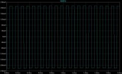
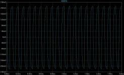
Let's damp it with your favorite 0.22 ohms resistor:
Amazing! Both the spikes and the ressonant effects are gone!
See, Graham, this is real life LOSS, and the speaker is connected to the source it was designed to.
Will this speaker sound different id connected to a 15 ohms source or to a 0.22 ohms sourece?
Absolutelly, it's in the traces.
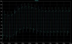
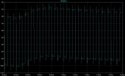
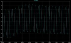
The right one is the 0.22, it's the closest reproduction of the input signal.
It just may be you like more the 15 ohms one, it's called 'euphonics', the embelishment of the sound by artificial means.
Amazing! Both the spikes and the ressonant effects are gone!
See, Graham, this is real life LOSS, and the speaker is connected to the source it was designed to.
Will this speaker sound different id connected to a 15 ohms source or to a 0.22 ohms sourece?
Absolutelly, it's in the traces.
The right one is the 0.22, it's the closest reproduction of the input signal.
It just may be you like more the 15 ohms one, it's called 'euphonics', the embelishment of the sound by artificial means.
Attachments
Jorge said:To it, let's apply a current 10 kHz square wave, band limited to 100kHz.
Hi Jorge ! Feeding a current squarewave into a coil is ... EVIL !
With a naked coil you'll get infinite voltage.
Where is the bandwidthlimit ?
Don't forget, an amp has voltageoutput and damping means the
ability to hold this voltage...
You really should do these sims with voltage-squarewaves !
Mike
I thought back-EMF refered to the conversion of electrical energy to mechanical and then some of the mechanical back to electrical. The voltage on an inductor in response to a suddenly applied current ramp is not back-EMF as I would use the term. BTW slew limiting a square wave does not band limit it.
Mauro
One can interchange voltage and current sources freely to study circuits behaviour.
Norton's theorem is used for the conversion.
See here:
http://hyperphysics.phy-astr.gsu.edu/hbase/electric/norton.html#c1
In my case, the resistors were in parallel with the current source (right figure in the link above)..
So, for the 15 ohms case it would be equivalent to a 15V voltage source in series with a 15 ohms resistor (short circuit current is 1A, open circuit voltage is 15V, same as it was the current source).
MikeB, Scott
I know the use of a current source is not recommended here (and the 3.5u rise time is not the best way to band limit), but it did good enough to show my viewpoint...
scott wurcer said:I thought back-EMF refered to the conversion of electrical energy to mechanical and then some of the mechanical back to electrical. The voltage on an inductor in response to a suddenly applied current ramp is not back-EMF as I would use the term. ...
Though understandably it may take a leap of faith, from the source perspective both are undistinguishable.
Position dependent nonlinearities and so forth on the other hand, are subsidiary to the analysis, not fundamental.
Rodolfo
Jan
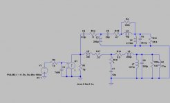
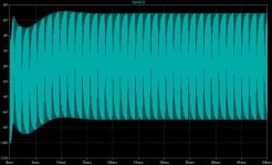
I've made the circuit more precise re band limiting, using a voltage generator and a transconductance to drive the speaker.
The band limit is done trough a single pole (set at 20kHz).
Due to some instability of LTSpice, I've placed a 100k resitor (R3) in parallel with the tweeter voice coil (a much higher value than the real equivalent loos resistence a more detailed model would have).
R1 is the source resistence, 15 ohms, 0.22 ohms or 1 G for infinite.
Results with a more precise band limit are the same, I've used 100kHz before since lots of amps do respond to this range.
Here's the circuit:
Attachments
Jorge,
Thanks! Very clear. There is one thing that still bothers me though. These error voltages we see in my opinion are the result of linear distortion, i.e. deviations in the freq response. Is that right? In other words, there are no non-linear distortions like harmonic or intermodulation products. Or was that clear to you from the start?
Jan Didden
ingrast said:
Though understandably it may take a leap of faith, from the source perspective both are undistinguishable.
Position dependent nonlinearities and so forth on the other hand, are subsidiary to the analysis, not fundamental.
Rodolfo
They are indistinguishable only in the sense that you excite a black box two-port with a current and you measure the voltage, i.e. for clarity most people do not refer to the V in V = L * di/dt as back-EMF. Maybe it's just semantics.
Compare the impedance curves of a speaker with and without the voice coil and cone clamped so they can't move. That would be a demo of with and without back-EMF (at least in the way I use the word).
The voice coil is not an issue and is not responsible for the so-called "back EMF". The case is mechanical/acoustical impedance transferred to the electrical side of the circuit (speaker in the cabinet). Should there be no mass, compliance, friction, acoustical compliance and acoustical mass, there would be no "back EMF". Just break the speaker and you will see the voice coil contribution.
PMA said:The voice coil is not an issue and is not responsible for the so-called "back EMF". The case is mechanical/acoustical impedance transferred to the electrical side of the circuit (speaker in the cabinet). Should there be no mass, compliance, friction, acoustical compliance and acoustical mass, there would be no "back EMF". Just break the speaker and you will see the voice coil contribution.
Carefully remove the voice coil and you will have no back-EMF, that I guarantee.
scott wurcer said:
.....Compare the impedance curves of a speaker with and without the voice coil and cone clamped so they can't move. That would be a demo of with and without back-EMF (at least in the way I use the word).
Perhaps this is a good place to settle once and for all the - by now infamous - controversy about back EMF or not.
If you clamp the speaker's moving parts, all mechanical contributions are dropped, that is, mass, friction and suspension/air compliance disappear. We might then say "well, then it is demonstrated back EMF relates with speaker mechanics and as such is unique".
Herein lies the fallacy, for the "back EMF" in the case of a speaker results from winding movement within a magnetic field while the "inductance" (*) EMF results from flux variation through a winding spanned cross section **BUT** the physics governing both phenomena are the same, thus making results indistiguishable.
To this, the fact as posted in the "back EMF" thread mechanical (mass, friction, elasticity) which obey differential equations identical in form with the ones governing electrical magnitudes (inductance, resistance, capacitance) allow to convert the hybrid model to a purely electrical one where the voltage-current relationships are equally identical from the standpoint of the driving source.
To round up, speaker "back EMF" has its roots on the same (transformer) electromagnetic interaction, and a whole speaker can be substituted for a purely electrical equivalent model which is indistingushable form the real one as seen from the amplifier. (To a fairly accurate linear approximation).
Rodolfo
(*) To be more precise actually, "transformer" EMF.
janneman said:These error voltages we see in my opinion are the result of linear distortion, i.e. deviations in the freq response. Is that right? In other words, there are no non-linear distortions like harmonic or intermodulation products.
Jan
Yes and no.
These simulations are based in linear models, so they do not take in account the non linear distortions that have been quite well covered in the Hawksford paper.
The only way to reduce them significantly is driving the speaker from a current source, but then linear distortions shows up (as in my previous postings with the 15 ohms or more source impedance).
So one has to decide - go the classical way (low output Z), or go to MFB.
Maybe it is possible to design a LF/MF (the area of most improvement due to current feed) speaker that benefits from a high Z amp (or a normal amp with a fairly high value resistor in series) and still has a flat response.
I really don't know if the results would be significant compared to real current feed.
I'm a few posts behind here.
Hi Andy,
You write that any audible effect must be subtle.
Yes, but it *is* there, and it is in the range of upper harmonic waveform content where we gain our subtle detail, characterising and positional cues.
Hi Jorge,
Cutting remarks are not nice are they ?
Ditto your incessant and personally aimed on-going accusations of 'religious position' !!!
We both know there are many underlying distortion mechanisms, so why do you always turn their resolution into argument instead of discussion ?
The scenario being discussed was extremely-low output impedance and a series output choke in order to investigate 'leading', loudspeaker current induced, choke voltage error.
You appear to be using resistors only; thus the voltage cannot be any other than directly and linearly related to loudspeaker current flow, with proportionate error voltage arising at all frequencies and being cross coupled between sections.
Hi Scott,
Is it not the alternating magnetic field generated back-EMF due to alternating current flow through an inductor that generates its increased impedance; a field that can separately, momentarily and independently either generate less or more back-EMF as the source waveform changes ?
The main back-EMF difference between a loudspeaker driver and an inductor is that the inductor is much more efficient.
Cheers ............. Graham.
- Status
- This old topic is closed. If you want to reopen this topic, contact a moderator using the "Report Post" button.
- Home
- Amplifiers
- Solid State
- The many faces of distortion