Sincerely, have tried with a resistance of 250ohm/20W and a choke with wire from 1mm of value about to 7-8 MH ( I not have not been able to it measure instrumentally ), and for generator to 50Hz has used an audio amplifier. Probably the "secret" is in the "Q" of the resonant circuit LC, and in the form factor of the 50Hz signal .
For the data that I have, from the curve 1 fig.3 seem that the energetic content to 50Hz is such by justify the 1000W of the resistance and the 15A of the choke.
Other point is the generator 50 Hz. Perhaps Hiraga has used a transformer or the pulsating output of a rectifier?
Mauro
For the data that I have, from the curve 1 fig.3 seem that the energetic content to 50Hz is such by justify the 1000W of the resistance and the 15A of the choke.
Other point is the generator 50 Hz. Perhaps Hiraga has used a transformer or the pulsating output of a rectifier?
Mauro
Indeed, the circuit LC even to seem me a function of filter.
For what concerns the analysis, at home I prepare ( besides launch generating DDS and sine -90 dB and the usual analogic oscilloscope ) of a tool of oscilloscopes for PC with working (Pico Tecnology ADC216) in real-time FFT. With this (economic) tool analyses real-time and without problems the harmonics till 160Khz with dynamic of 90 dB ( has 16bit "realities" of vertical resolution ).
Naturally is not the precision one, but for this kind of measures not are of interest hardly ever the absolute value of a measure but her general "envelop" (the graphics are a very hard harmonics saturation!)
ciao
Mauro
mauropenasa said:Indeed, the circuit LC even to seem me a function of filter.
[snip]ciao
Mauro
Yes, the filter is there to isolate the 50Hz generator from the amplifier, to keep the 1kHz out of the 50Hz generator, and to avoid that the 50Hz generator short-circuits the amplifier output, which would be a Bad Thing
")
Jan Didden
I have made curious me. I will do of the tests the more ample, and if have resulted of relief there will show them.
In fact I hopes to verify the importance of this parameter (MFB immunity) in the "sonic" quality, and the adeguate topology to realized.
This are the intellectual "challenges" that like me!
Ciao
Mauro
In fact I hopes to verify the importance of this parameter (MFB immunity) in the "sonic" quality, and the adeguate topology to realized.
This are the intellectual "challenges" that like me!
Ciao
Mauro
mauropenasa said:I have made curious me. I will do of the tests the more ample, and if have resulted of relief there will show them.
In fact I hopes to verify the importance of this parameter (MFB immunity) in the "sonic" quality, and the adeguate topology to realized.
This are the intellectual "challenges" that like me!
Ciao
Mauro
Mauro,
Very interesting! I'm looking forward to your findings!
Jan Didden
...gain is all you need
jeeze guys, the answer has only been known for over 60 yrs (70 yrs if you credit Bode and the boys at Bell having worked it out prior to WWII, just wasn’t well published before Bode’s book)
maybe some around here should really read up on feedback theory rather than repeat inanities they've picked up on the web and in audio magazines
all you need is low output impedance; anybody ever see: Vout = Itest * Zout in some textbook?
and of course there is only one practical method of achieving low output Z in a world of controlled current sources (like transistors or power fets) - that’s by applying lots of negative feedback, be it local or global
to get output Z low enough for the test current (or the norton -equivalent of "back EMF") to give "interface intermodulation" products down among the other distortion floor products all you need is gain - negative feedback loop gain around the output stage to be more specific
remember that emitter followers are 100% local negative feedback stages, go for a triple cfp/darlington output and most amps could do a good job if properly biased and compensated
http://www.diyaudio.com/forums/showthread.php?s=&postid=473194&highlight=#post473194
shows more gain = lower Zout and lower “interface intermodulaion” even though the JLH and Graham’s modification don’t have a excess of output stage current gain, maybe some else here besides myself and amplifierguru could benefit from reading the references in that post
( I do have sims showing this “interface distortion” @ -140 dB – this is one case where spice has a good chance of getting the “distortion” number close to right since it is determined by Zout)
I have tried launch amplifiers ( all with a tall degree of local or general NFB ) and the resulted on a range of 90 dB am as defined by jcx ( Low Zout = low "interface distorsion "). In practice not distinguishes a substantial variation of THD.
Even I believe that the strong THD of the curves publish are reproducible only in structures with high Zout & /or low factors of NFB ( totem pole & single ended without NFB?).
To show it I have to reconstruct some single ended.
If some disposes of this amplifiers and it may try, he is the welcome!
Ciao
Mauro
Re: ...gain is all you need
jcx,
No need to convert me, I'm in the same camp. But if you look at the graphs in the article, one can only conclude that apparently there are a lot of incompetent designers around. Or maybe they are competent, but deliberately design 'bad' amps because low feedback is the current rage, and the current rage is where the money is.
Jan Didden
jcx said:[snip]all you need is low output impedance; anybody ever see: Vout = Itest * Zout in some textbook? [snip]
jcx,
No need to convert me, I'm in the same camp. But if you look at the graphs in the article, one can only conclude that apparently there are a lot of incompetent designers around. Or maybe they are competent, but deliberately design 'bad' amps because low feedback is the current rage, and the current rage is where the money is.
Jan Didden
Re: ...gain is all you need
You are absolutely right jcx .... at DC.
Enter s # 0 and it more or less quickly falls appart.
Don't get me wrong, I vow for negative feedback all the time, only we must be aware where departures lay, and deal with them to the best of our resources.
Rodolfo
jcx said:.....and of course there is only one practical method of achieving low output Z in a world of controlled current sources (like transistors or power fets) - that’s by applying lots of negative feedback, be it local or global
......
You are absolutely right jcx .... at DC.
Enter s # 0 and it more or less quickly falls appart.
Don't get me wrong, I vow for negative feedback all the time, only we must be aware where departures lay, and deal with them to the best of our resources.
Rodolfo
Excuse me, sirs, I would like to contradict. There are many ways to Rome. While it is true, that a HIGH CURRENT CAPABLE, low Zout voltage amplifier would give a good result here, [How many amps will flow in the, say, 20 mOhm output inpedance?], in the real world I would not be surprised if such a high feedback amp eventually would loose the fight half way up, and, while running out of current, would produce something like the fig. 3-3; fig 3- 4.
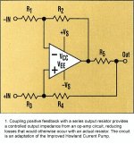
In the meantime, in my opinion, the fig 3 - 2. results could easily be reproduced by a Howland current pump, shown by the figure below, and proposed many times on this forum by Mauro, who includes it in his designs. Also the ESP project 56 would fit, although the actual measurement setup should be changed for testing it. But in the real life, with a real speaker it would behave exactly the same, if configured
to a high enough output impedance. A tube amp, while having a high output impedance, it is NOT a controlled impedance, and also comes with a high THD figure, this is how fig. 3 - 5 is generated.
I have a slight suspicion, that also Hiraga had something similar in mind, this is why fig. 3- 2 has the caption put in this way:
Output signal of an amplifier presenting a very good performance at
THIS test...
Otherways, unfortunately I haven't red the article, yet, so I might just talking silly here.. Please feel free to bash me..
On the other hand, I would have just stayed silent, if that project 56 presently in work at home would not sound really pleasing..
Ciao, George
Attachments
I am getting ready a variation of the Hiraga setup to make + evident the phenomenon of intermodulation.
The first results are in favor of the Hiraga theories, in the sense that injecting of the harmonicas on the load form of the intermodulations| with envelop diverged for every amplifier, don't tie to the dumping factor but to the intrinsic characteristics of the NFB (local and global) . to lend
Mauro
Joseph K said:Excuse me, sirs, I would like to contradict. There are many ways to Rome. While it is true, that a HIGH CURRENT CAPABLE, low Zout voltage amplifier would give a good result here, [How many amps will flow in the, say, 20 mOhm output inpedance?], in the real world I would not be surprised if such a high feedback amp eventually would loose the fight half way up, and, while running out of current, would produce something like the fig. 3-3; fig 3- 4.
In the meantime, in my opinion, the fig 3 - 2. results could easily be reproduced by a Howland current pump, shown by the figure below, and proposed many times on this forum by Mauro, who includes it in his designs. Also the ESP project 56 would fit, although the actual measurement setup should be changed for testing it. But in the real life, with a real speaker it would behave exactly the same, if configured
to a high enough output impedance. A tube amp, while having a high output impedance, it is NOT a controlled impedance, and also comes with a high THD figure, this is how fig. 3 - 5 is generated.
I have a slight suspicion, that also Hiraga had something similar in mind, this is why fig. 3- 2 has the caption put in this way:
Output signal of an amplifier presenting a very good performance at
THIS test...
[snip]
Hi George,
Reading your above comments, I assume you agree that in any case good results depend on high feedback. A Howland current pump, having high output impedance, will absolutely produce something like fig 3-2, because the high output impedance results from strong feedback. A tube amp, which, as you say has also high output Z, will NOT nearly faire as well, precisely because the high Zout does NOT result from strong feedback! So, I guess we are all singing from the same sheet of music after all.
I looked at the original (French) caption of 3-2, I quote:
"Courbe 2: signal obtenue a la sortie d'un amplificateur presentant un tres bon comportement sur ce test"
I don't think his (Hiraga's) emphasis is on THIS (CE) as you assume, I would think that if so, he would have used "CETTE", but I will yield to the real Francophiles at this forum.
Jan Didden
Dear Mauro!
It sounds interesting! I'm looking forward to Your results!
In the meantime may I point out, [about YOUR own circuit.. so you surely know it better than me] that this Howland Current Pump does exactly this - applies a tricky feedback topology, which process the input signals present between -IN and +IN differentially, and rejects
the external signal forced upon its output, because it will show up accross the feedback networks, like common mode!
[because R5 is chosen to be small in practice, and the open loop output Z is not small]
The byproduct of this type of functionality is the high output impedance, low damping factor.
Jan!
Yes, we absolutely agree about the importance of the high feedback here! Then, obviously, it was only a guess from my side about Hiraga's original intentions..
But, I would like to note, that not only the figure 3- 2 diagram can be reproduced by a high output Z device, but also it CAN NOT BE reproduced by a low output Z device [ we would see only 1kHz]!
For me it's quite a proof that he used some kind of current generator.
Ciao, George
But, I would like to note, that not only the figure 3- 2 diagram can be reproduced by a high output Z device, but also it CAN NOT BE reproduced by a low output Z device [ we would see only 1kHz]!
George, that's quite opposite to JCX suggest. I dont know which is right.
But your opinion that this yields from true "current source" power amp is a good option here.
Do you think NP's FirstWatt can give graph2?
Jcx holds my maximal full respect - for me, he is a master. [Just an example - what do you think, who was the absolutely first to suggest OPA660 & AD844 as open loop I/V, in this small internet forum galaxie? And having also a first estimate about the possible differencies between them?]
But in this case, I think he was talking about the back -EMF problem in general, and not considering that special diagram. [Excuse me, jcx, I know that You hate even that term..]
The First Watt, I have to admit, I don't know. Mauro is right when saying that high output impedance in itself is not enough - You need the special feedback arrangements as well. Now I should go & check Nelson's design, I should have done it just a long time ago, in the first place..
Ciao, George
How much first will exchange with you the data that are picking up ( inclusive the setup that is using ).
Cash advance that the howland current punp even with this test confirms my theories ( the V/I translation and the High Zout reduces the negative effects of overall feedback, and the bridge involves as a BJT with local NFB ). This however denies the Joseph hypothesises in connection with the curve 2: My circuit behaves as curve 5, or as an valve amplifier . For the curve 2 have to do other test, but I anticipate that simply is gotten with very lower open loop Zout ( Power local NFB ) or ( in accordance with me ) with circuits to negative impedance.
Ciao
Mauro
- Status
- This old topic is closed. If you want to reopen this topic, contact a moderator using the "Report Post" button.
- Home
- Amplifiers
- Solid State
- The many faces of distortion