I remember now why the power supply bounced and oscillated heavily: I had as section after the supply, 56.000 muF capacitors. That is why they were completely opened up to maximum conductivity. The schema has 8 muF and a formal stopper resistor even to reduce the output current. I should try it again that way!
albert
That's not to limit the output current. It prevents the supply from high frequency oscillation.
I've built many of these power supplies, all buffered by high capacities at their regulated exits. None ever showed oscillation.
Dear all,
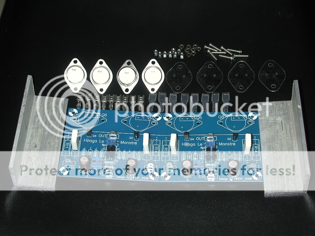
I got myself a le monste kit from ebay.
But I found that the amplifier board has a 9V DC-Offset without speaker connected and 4.9V with a 6Ohm speaker connected.
Using
 these pcbs. I solderd a 1.2K as R1 (input resistor) and 1K on R2 and R3.
I also tried: R1=1k and R2=R3=470 and R2=R3=235.
The other components are the same as these:

I can't think of another solution. Can you please help me?
As power supply I'm using a: 2x22V 300VA transformer with a rectifier bridge and a 4x(15000uF @ 63V) capacitor bank.
Hope you can give me some advise,
Duco
I got myself a le monste kit from ebay.
But I found that the amplifier board has a 9V DC-Offset without speaker connected
and 4.9V with a 6Ohm speaker connected. Using
I also tried: R1=1k and R2=R3=470 and R2=R3=235.
The other components are the same as these:
I can't think of another solution. Can you please help me?
As power supply I'm using a: 2x22V 300VA transformer with a rectifier bridge and a 4x(15000uF @ 63V) capacitor bank.
Hope you can give me some advise,
Duco

Duco, the transistors and selected FETS deviate from the originals (a lot) so indeed you should change the resistors value.Dear all,
I got myself a le monste kit from ebay.
But I found that the amplifier board has a 9V DC-Offset without speaker connected
Usingthese pcbs. I solderd a 1.2K as R1 (input resistor) and 1K on R2 and R3.
I tried: R1=1k and R2=R3=470 and R2=R3=235.
Duco
Having a DC value means that you have too little 'room' in the potmeter to accomodate for this DC point.
No problem:.
I suggest a potmeter of 2K5 parallel of the R2R3's. Then you can bias the unit just like is written in the F5 thread in the Pass sections (the Le Monstre works just like the F5; only difference is the other type of output configuration: MosFET versus inverted Darlington).
I bought my devices at the shop of Hiraga (lucky) and ititially went for 910 ohms; but I reimplemented it various times. As I lowered the powerline from 14 volts to 13 volts and reduced the current too I found it necessary to reduce the original value from 1 k to below 900 ohms; and all the time inserting new values drove me mad.
@triode_al
Thanks for your comment
You say, mount in addition a 2k5 potmeter parallel to the R2=1k and one parallel to the R3=1K?
This way a have 3 potmeters and I'll be able to adjust the bias the a proper value?
Yours,
Duco
Put your P1 (on the sources) in the mid position; then you can select the DC bias current on both halves independently (call them P2 and P3 now).
When you have the correct bias and about the correct DC point you can leave it like that.
As I see it: Having 31 V rails on this MONSTRUM SUPERBUS is no problem (as long as the output pairs can handle this voltage and the heat).
Bought 2K2 potmeters, they didn't have 2k5. Soldered them parallel to R2 and R3 on places R4 and R5.
Only when I change R5 does the DC-offset drop. I can get it lower than 10mV but it sound awfully horrible. When I change R4 nothing happens.
When DC-Offset is 4V with speaker connected it sounds all right, not perfect and has a slight bee in the box. But that just gets me right where I began.
-Duco
Only when I change R5 does the DC-offset drop. I can get it lower than 10mV but it sound awfully horrible. When I change R4 nothing happens.
When DC-Offset is 4V with speaker connected it sounds all right, not perfect and has a slight bee in the box. But that just gets me right where I began.
-Duco
another tip: Increase R6/R9. In the original it was 2k-2k voltage divider (about 12V rails).
With 24V it would be 3k9/2k and with 34 volts I suggest 10 to 12Kohms.
(I have a cascode input up and running with 20k/5k on 37 V rails and that works like a charm. A wrong value ends up with sonic impact, I found out.)
You should not hear the hum when it is balanced right.
Did you check the Idss of the input pair to ensure they very well matched?
Bought 2K2 potmeters, they didn't have 2k5. Soldered them parallel to R2 and R3 on places R4 and R5.
Only when I change R5 does the DC-offset drop. I can get it lower than 10mV but it sound awfully horrible. When I change R4 nothing happens.
When DC-Offset is 4V with speaker connected it sounds all right, not perfect and has a slight bee in the box. But that just gets me right where I began.
-Duco
Duco,
I'm just pondering about this:
the best way is to start with both R4/R5 (the two pots now connected) at zero, and then iteratively increase the resistance until you have the required DC current (idle) that can be measured across R11/R12. There should be a second voltmeter on the output.
You could but do not need to have a resistance of 50 ohms on the output.
Take the top as example: Q4 needs 0,6 volts Vbe and R11//R12 take is 1 amp*0,47 (isn't that your total resistance?) so at the emitter of Q1 you should have about 1,0 to 1,1 volts. Having 0,8x volts there will give small bias current of just 0,5 amp.
The nice thing about this procedure is that it works too with different classes of Idss of the fets.
I hope you have a good pair of Q4 with ample current capability and very lineair Hfe: with higher voltage these can easily saturate.
Buy the way - - How do you connect a speaker when there is 4 volts on the output?

Hello,
Has anyone tried using NJW0281 and NJW0302 for the output stage in Le Monstre? I am thinking of changing only these from original schematic. I know Sigurd Ruschkow is using these but his amplifier is running at more than 2 amp idle current. How about using these devices at lower current (~0.8A). They has higher Cob than the original Toshiba transistors, but I am not sure if this affects the sound at all. Any impressions ? Comments?
Thanks,
Simeon
Hey ,i am new at the forum.I just bilt the 8 watt amplifier Hiraga.
Wheni put power on the circuit ther is a problem.On the negative site i misure a voltage on the 1k resistor but not on the positive site.Any a idee what cold be wrong?
Wheni put power on the circuit ther is a problem.On the negative site i misure a voltage on the 1k resistor but not on the positive site.Any a idee what cold be wrong?
An externally hosted image should be here but it was not working when we last tested it.
@triode_al
Thanks for your comment
You say, mount in addition a 2k5 potmeter parallel to the R2=1k and one parallel to the R3=1K?
This way a have 3 potmeters and I'll be able to adjust the bias the a proper value?
Yours,
Duco
The higher the IDSS of the JFETs the higher the bias. Jean Hiraga operated FETs of Y suffix and an IDSS of significantly lower than 2,5mA.
Try to find transistors of the lowest possible IDSS and decreace the value of the 1k resistors. It is preferable to match the pair close but not a must.
To adjust a proper bias of say 600mA, substitute the resistors by 1k Pots trimmed to 500R. Let the amp warm up and measure the voltage across the collector resistors of both transistors in the output stage (V is equivalent to A). If the bias is too low, increase the values of both (!) trim pots to the same value and vice versa whether it's too high. Allow the amp to warm up again and control the bias again. It might be necessary to repeat the procedure more than one time. Once you have found the proper bias, measure the trimmed value of the pots and change them with fixed resistors of that value.
Voilà, your Le Monstre will work stable for many years!
Last edited:
- Home
- Amplifiers
- Solid State
- Hiraga "Le Monstre"