BTW, where does the 1.3mA figure come from? (Post #1181, perhaps?)
Unless I'm mistaken (and I quite often am), the 1.3mA is not the IDSS of the JFET itself, but rather the ID an average Y grade JFET (IDSS ~2mA) would pass when degenerated by 50R (1/2 of the 100R trimmer). Which would mean that a JFET from the very bottom of the GR grade range (IDSS ~2.6mA) should get you pretty close to the target.
A trusted seller of the Toshiba JFETs and a member of this board, alweit, used to be able to supply the lowest possible IDSS GR grade parts specifically for Le Monstre builds in the past - not sure if he still has some available, but there's no harm in asking...
I have done some testing on a third pcb with 2SJ103/2SK246 Y-grade i do have.
Got about 1,44V/1,46V over the 1Kohm resistors, pretty ok I think.
Did not have too many of those rare one´s so they are not properly matched.
Decided to stay with 2SK170/2SJ74 GR with low IDSS and adjust the design a bit.
My 4 lowest 2SK170 GR IDSS values are:
3.005mA - 3,147mA
Ordered 4 matched pair of 2SJ74 GR from punkydawgs with about the same IDSS as I already have.
The 1,3mA IDSS is probably a misunderstanding due to someone mentioned it should be about 1,3V over the 1Kohm resistor.
You have right, Y-grade will probably be around 2mA or something.
I saw a post someone highered the bias voltage to 1,5V to get even more bias current in the output stage.
I will test this and adjust the 1Kohm resistor down to the right value once I got the pair I will use.
I have got very large heatsinks so heat will not be a problem.
Maybe the batteries drain a bit faster.
Today I have to charge the batteries every 3-4 weeks depending on playing.
I hope they come soon, the last ordered 2SJ74gr´s was probably lost in transportation.
Does anybody tried to use a capacitor multiplier as a power supply to 8W Hiraga?
Since, the biggest "problem" of this amp is the huge power supply, a capacitor multiplier sounds like a good and far cheaper, solution.
Or it's too good to be true?
I'm planning to use the ripple eater (Simple Ripple Eater PSU for the sx and kx-Amplifiers).
This PSU is designed for the Ovation SX Class A, which is enough similar to Le Monstre and it's power it's almost double (15W).
Your opinion would be much appreciated.
Daniel
The amplifier then should have less power supply ripple for lower cost, but it will also sound (completely) different since the power supply transistors would be an active part of the amplifier itself.Does anybody tried to use a capacitor multiplier as a power supply to 8W Hiraga?
Since, the biggest "problem" of this amp is the huge power supply, a capacitor multiplier sounds like a good and far cheaper, solution.
Or it's too good to be true?
Hello,
Today i read some results about power supplies mainly for the 20 and 30 watt Hiraga. Just a few about le monstre all published on French websites.
Some smps were better than expected. Some people preferred the solution with BIG caps.
The general idea was that there are some parts in the supply that must work really hard because there is not much energy storage because caps are small. Lots of smps sounded better with high quality film caps close to the amp circuit.
I think both capacitor multiplier and smps depend upon the " sonic signature " of the active parts added. These active parts are kind of forced to work hard because the amp still needs a beefy supply.
Greetings,Eduard
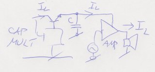
But the capacitor multiplier transistors has nothing to do with the audio path.
How can this happen?
If the capacitor C in the figure is small, all the current variation to the load is passed through the pass transistor in the capacitance multiplier. The only way here to reduce the current variation through this pass transistor is to increase the capacitor value to very large value. Then the reason to use the capacitance multiplier is strongly reduced, but worse, you will risk to introduce instability in the capacitance multiplier...
Attachments
Finally got some 2SJ74 GR jfets now.
No really good pairs jet but will get some more jfets soon.
Done some final test to get the right values of the resistors together with the GR jfets.
Started with R4/R5 = 560ohm.
Got about 1,26V over R4/R5
Added a 33ohm resistor to 593ohm
Got about 1,36V now.
Replaced the 100ohm pot with 2 metal film resistors with lower values but still the same ratio.
R14 = 22ohm / R15 = 47ohm
(Because of some mismatch in the jfet pair and difference in the power supply voltages +12,1V / -11,7V)
My choice will be 2x33ohm if the DC offset voltage is still low.
After the adjustment I got about 1,43V over R4/R5.
The final adjustment was to change R4/R5 to 600ohm.
(1Kohm in parallell with 1,5Kohm)
Now the voltage is slightly over 1,45V.
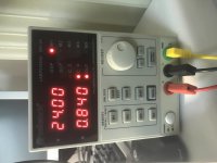
818mV over R10/R11 and the current is 818mA at the final stage.
Total consumption is about 840mA at 24V.
I think this will be a good compromise between performance and battery power.
I´m using 2x80Ah AGM battery´s as the power source.
The sound was improved from the start with 1,26V over R4/R5 to finally 1,45V, no doubt about that.
Because of the test PCB the sound was in mono.
I´m thinking of limiting the bandwith a bit by adding a 470pF capacitor C2 in parallell with R12.
Not sure about this but I added it during the test.
Please help me here.
I will measure the design with the scope tomorrow to see everything is alright.
No really good pairs jet but will get some more jfets soon.
Done some final test to get the right values of the resistors together with the GR jfets.
Started with R4/R5 = 560ohm.
Got about 1,26V over R4/R5
Added a 33ohm resistor to 593ohm
Got about 1,36V now.
Replaced the 100ohm pot with 2 metal film resistors with lower values but still the same ratio.
R14 = 22ohm / R15 = 47ohm
(Because of some mismatch in the jfet pair and difference in the power supply voltages +12,1V / -11,7V)
My choice will be 2x33ohm if the DC offset voltage is still low.
After the adjustment I got about 1,43V over R4/R5.
The final adjustment was to change R4/R5 to 600ohm.
(1Kohm in parallell with 1,5Kohm)
Now the voltage is slightly over 1,45V.
818mV over R10/R11 and the current is 818mA at the final stage.
Total consumption is about 840mA at 24V.
I think this will be a good compromise between performance and battery power.
I´m using 2x80Ah AGM battery´s as the power source.
The sound was improved from the start with 1,26V over R4/R5 to finally 1,45V, no doubt about that.
Because of the test PCB the sound was in mono.
I´m thinking of limiting the bandwith a bit by adding a 470pF capacitor C2 in parallell with R12.
Not sure about this but I added it during the test.
Please help me here.
I will measure the design with the scope tomorrow to see everything is alright.
Attachments
Last edited:
or make good regulators
Details please.
Shematic & pcb will be useful.
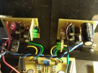
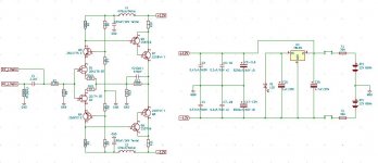
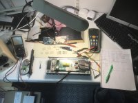
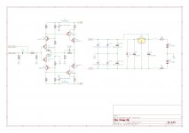
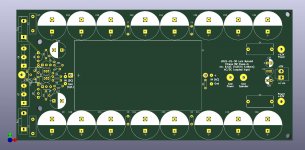
Here is a better view of the schematic and some PCB pic´s.
In this latest version of the PCB I have put in an optional 100ohm pot P1so you can choose between using 2 resistors or a pot.
Also expanded the holes for the Mundorf 1ohm resistors and moved the lanes a bit to clear the area near the screw holes.
Added a few millimeters to the size of the PCB to get a better placement of the screw holes in the right side.
Also replaced the to-92 to a wide TO-92 (Q5/Q6) so you don´t have to bend the legs.
Separated the TX-2575 resistors little so they will not be to close to each other.
The PCB in each TX-2575 has some corners sticking out a bit and I had to place some of them 2mm higher from the PCB to not touch each other.
Attachments
Last edited:
While I applaud the improvements to the original circuit, I have to stop and ponder at what point do we deviate from the original circuit and it's intended sound? Granted, there are much lower noise active devices available that would be much better suited to regulated rails, etc. The Le Monstre is a raw, simple circuit that has no temperature, voltage drift, etc. compensation. There are other topologies that seem to warrant these improvements better.
I ask the question because I myself plan to build the Hiraga Le Monstre and have all the parts in-hand for the original design as Hiraga intended. I even plan to test the battery PS and modern wheelchair batteries seem to perfectly fit the bill. The only mods I have made were to replace obsolescent parts with equivalent replacements.
So, chime in and convince me to continue on the Hiraga "purity" path or should I diverge? Not looking to stir the pot, looking for an education.
FWIW, I did design a single-PCB solution with modern components but then digressed back to a simply point-to-point power supply with PCB's for the signal as the original was designed. My thought process being to replicate the acclaimed original design as close as possible.
I will just speak for my self.
I have spent days/weeks to get the right Toshiba transistors.
The 2SK170/2SJ74 Y-grade jfets is extremely hard to get.
Impossible to get really otherwise it will probably be fake´s.
You have to use GR-grade and in that case you have to modify the resistor values to get the design working.
It is a compromise, I know, but it´s the only solution I know of.
The modern version on the Internet using BC550/BC560 and TIP3055 is another solution.
My first Hiraga amplifier was built around this new design.
Sound´s really well.
In my new project I would like to use the original components like you do.
Unfortunately you have to buy vintage amplifiers like Teac A70 to get the 2SK170 Y grade jfets.
I have researched this too but it´s a long and expensive way to take.
The 2SJ74 Y is even harder to get.
Matching them will probably rise the problem 10 times more.
Except them all is like the original design, only modern capacitors and resistors.
The PCB design gives you the opportunity to fit and place the components where you want them.
Last edited:
I think that in Le Monstre the BL's are used. Am I wrong?
To be exact, the Y's are used that is similar to the BL's.
No and no. See post 1181:
Hiraga "Le Monstre"
Last edited:
I noticed that you make strong comment even without concrete fact, this will put you in a bad light.To be even more exact, not similar but nonexistent.
Taken from Toshiba Small Signal Transistor Semiconductor Data Book 1983.
Attachments
- Home
- Amplifiers
- Solid State
- Hiraga "Le Monstre"