In the interim I disconnected the R20 and connected base of T7 to ground to see any difference but nothing Output voltage swing remains 41volt max.
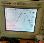
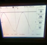
Attached image of rail voltage and output swing @29hz
Can any one suggest me a way to measure voltage across 0.33 ohm source resistors while feeding 29hz @40volt peak on output rails.
My multimeter measured 27 mV across the 0.33, in DC range which does not add for said output.While trying to measure with oscilloscope I noticed ground looping and noise, my oscope is not isolated.
Regards
Attachments
Last edited:
You must not try to measure across the source resistor with a grounded oscilloscope probe. The grounded link will blow up your amplifier.
A stand alone battery powered meter can measure across the source resistor.
When the load is removed and the input is shorted you can measure the output stage Vre/Vrs bias voltage. This will tell you the current if you know the resistor value.
There is no value in trying to measure the AC voltage across the source resistor when the amplifier is shorted input.
If you measure from Output to Signal return you can see the output noise+hum whenon the mVac scale and see the output offset when on the mVdc scale.
Thanks Andrew, I got it now.You must not try to measure across the source resistor with a grounded oscilloscope probe. The grounded link will blow up your amplifier.
A stand alone battery powered meter can measure across the source resistor.
There is no value in trying to measure the AC voltage across the source resistor when the amplifier is shorted input.
If you measure from Output to Signal return you can see the output noise+hum whenon the mVac scale and see the output offset when on the mVdc scale.
When the load is removed and the input is shorted you can measure the output stage Vre/Vrs bias voltage. This will tell you the current if you know the resistor value.
What is Vre and Vrs ?
I hope you meanVre = Voltage across Re
Vrs = Voltage across Rs
Vre= Voltage across load resistor
Vrs= Voltage across source resistor
?
Just to double confirm.
Happy to say that I figured out the issue. It was input transistors,
I thought why not give it a try for a fresh pair of C1845.The previous Transistors were of different make and showed Hfe of <40 while the current one is showing >150 in multimeter.
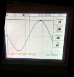
Now the Output swings touching Vrails without clipping.Will Post Screen shots soon.
Thanks to all suggestions and support .
Rgds.
I thought why not give it a try for a fresh pair of C1845.The previous Transistors were of different make and showed Hfe of <40 while the current one is showing >150 in multimeter.
Now the Output swings touching Vrails without clipping.Will Post Screen shots soon.
Thanks to all suggestions and support .
Rgds.
One thing I remember - the clipping will be non-symmetrical.
Lower half clips sooner than upper (or the other way around).
Quasi was working on it to make it symmertrical, but in the end
it wasn't worth it...
There was a fix from someone else involving Bandaxall diode
in the lower half, that helped a little...
Lower half clips sooner than upper (or the other way around).
Quasi was working on it to make it symmertrical, but in the end
it wasn't worth it...
There was a fix from someone else involving Bandaxall diode
in the lower half, that helped a little...
Happy to say that I figured out the issue. It was input transistors,
I thought why not give it a try for a fresh pair of C1845.The previous Transistors were of different make and showed Hfe of <40 while the current one is showing >150 in multimeter.
Now the Output swings touching Vrails without clipping.Will Post Screen shots soon.
Thanks to all suggestions and support .
Rgds.
Thanks for the reminder Minek123,One thing I remember - the clipping will be non-symmetrical.
Lower half clips sooner than upper (or the other way around).
Quasi was working on it to make it symmertrical, but in the end
it wasn't worth it...
There was a fix from someone else involving Bandaxall diode
in the lower half, that helped a little...
I thought it was again some anomaly with components.
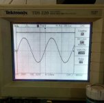
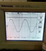
Screenshots attached.The waveform is with 4 ohms loudspeaker connected.
Anyway I am going to drive my home subwoofer with this ,I wasn't happy with Class D amplifier hence the transition..
Attachments
All the 6 mosfet on negative rail failed along with fireworks of gate resistor 27 ohm .
Amp was warm playing around moderate volume when I disconnected the Input from the mobile phone.Heard a loud pop and noticed gate resistors smoking.
Desoldered all the 6 mosfet,it shows Gate to Source shorted. Gate protection diode 8.2volt is fine.
Please advice why mosfet failed abruptly ?
Regards.
All the 6 mosfet on negative rail failed along with fireworks of gate resistor 27 ohm .
Amp was warm playing around moderate volume when I disconnected the Input from the mobile phone.Heard a loud pop and noticed gate resistors smoking.
Desoldered all the 6 mosfet,it shows Gate to Source shorted. Gate protection diode 8.2volt is fine.
Please advice why mosfet failed abruptly ?
Regards.
8.2volt Zenner diode is in shorted state ,I wrote Fine instead of
I still haven't been able to figure out as how exactly the Mosfets failed.But I am now sure it was due to oscillations but where.
There seems to be a lot of information on Mosfet failure on the internet . From what I read so Far this could any of the below reasons..
1.Oscillations from Input (Input cable was 1 meter long shielded wire with 3.5mm stereo socket directly soldered into amp without volume control)
I heard a loud pop sound and probably Mosfet shorted and protection triggered
2.Parasitic oscillation at Gate (which zenner diodes are useless to prevent above 1mhz)
I thought with a 330 ohm shunt resistor at the gate of the Mosfet , chances of high voltage is very rare, added with an 8.2 volt zenner.
But Sh** happened ,mosfet are fried along with the Zenner. Probably the oscillations didn't start here but the from the Loudspeaker.
3. Transient spike from Loudspeaker which body diode couldn't absorb.
Thinking of adding a Schottky diode parallel to the Mosfet?
And
4. All of the above at once like a chain reaction -hell broke loose instantly.
Those 6 pairs of Fets are not matched ,But for a Linear amplifier ,I guess that doesn't matter much.
Regards.
Bob Cordell recommends small Zobel circuits (R + C) between Gate and Drain of each mosfet.
If I remember correctly 47pF and 100Ohms, check out in his book (must be available somewhere on the net).
If I remember correctly 47pF and 100Ohms, check out in his book (must be available somewhere on the net).
I still haven't been able to figure out as how exactly the Mosfets failed.But I am now sure it was due to oscillations but where.
There seems to be a lot of information on Mosfet failure on the internet . From what I read so Far this could any of the below reasons..
1.Oscillations from Input (Input cable was 1 meter long shielded wire with 3.5mm stereo socket directly soldered into amp without volume control)
I heard a loud pop sound and probably Mosfet shorted and protection triggered
2.Parasitic oscillation at Gate (which zenner diodes are useless to prevent above 1mhz)
I thought with a 330 ohm shunt resistor at the gate of the Mosfet , chances of high voltage is very rare, added with an 8.2 volt zenner.
But Sh** happened ,mosfet are fried along with the Zenner. Probably the oscillations didn't start here but the from the Loudspeaker.
3. Transient spike from Loudspeaker which body diode couldn't absorb.
Thinking of adding a Schottky diode parallel to the Mosfet?
And
4. All of the above at once like a chain reaction -hell broke loose instantly.
Those 6 pairs of Fets are not matched ,But for a Linear amplifier ,I guess that doesn't matter much.
Regards.
Gate Zobel Networks
Rather than just killing the high-speed performance of the MOSFET, it is better to reduce
the
Q
of the circuits involved in the oscillator topologies and damp out the oscillations.
This can be done with series R-C Zobel networks like those used to shunt the output of
power amplifiers [6]. These circuits look largely like open circuits at audio frequencies,
but transition to a fairly low-value resistance at high frequencies. When placed in the
gate circuit of a MOSFET, these networks provide a resistive shunt at the high frequen-
cies where parasitic oscillators are likely to be formed.
These Zobel networks are usually best connected from gate to drain, rather than
from gate to ground. This forms a damping loop with the drain that is more local at
high frequencies. Typical values for the components of a gate Zobel network are 47 Ω
and 100 pF [6]. It is also important to minimize inductance in the gate line from the
driver transistor. Recognize that only 100 nH of inductance has an impedance of 63
Ω
at
100 MHz.
Bob Cordell recommends small Zobel circuits (R + C) between Gate and Drain of each mosfet.
If I remember correctly 47pF and 100Ohms, check out in his book (must be available somewhere on the net).
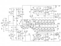
Redesign and improvements ACRTK400
Hi cold raining days coming,....
I spend last weekend time to redesign Quasi ACRTK400 and add improvemnts
I did not test circuit now !!!
Any ideas for improvemnets or faults in schematic before make PCB ?
1. Discrete Input Stage from ACRTK400 replace with OP AMP LM318
No DC Offset adjustment required,
Offset will adjust with R4 /C4 - 4,7K and 47pf @ Pin 1 from LM318 IC
Input Stage circuit design with LM318 is from BGW 750B PA Amplifier
2. T4 / T2 MJE 350 divide the signal into positive and negative compnents
3. Triac Crowbar DC Protection switch Output to Ground if DC Offset > 30V
Relais DC protection cant reliable protect Speaker Rails > +/- 50 V DC
Triac Crowbar DC Protection work 100 % reliable, had protect my speaker in the past and save my money
1 - 2 - 3 coming from big power PA Amplifier and working reliable
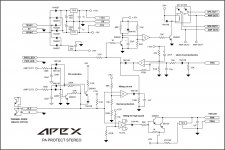
4. Have add Over Current and Short Circuit detect from APEX AX16
5. Apex PA Protect circuit for H900 / B500 can add to over current detect circuit.
4 - 5 is from diyaudio member APEX
Hi cold raining days coming,....
I spend last weekend time to redesign Quasi ACRTK400 and add improvemnts
I did not test circuit now !!!
Any ideas for improvemnets or faults in schematic before make PCB ?
1. Discrete Input Stage from ACRTK400 replace with OP AMP LM318
No DC Offset adjustment required,
Offset will adjust with R4 /C4 - 4,7K and 47pf @ Pin 1 from LM318 IC
Input Stage circuit design with LM318 is from BGW 750B PA Amplifier
2. T4 / T2 MJE 350 divide the signal into positive and negative compnents
3. Triac Crowbar DC Protection switch Output to Ground if DC Offset > 30V
Relais DC protection cant reliable protect Speaker Rails > +/- 50 V DC
Triac Crowbar DC Protection work 100 % reliable, had protect my speaker in the past and save my money
1 - 2 - 3 coming from big power PA Amplifier and working reliable
4. Have add Over Current and Short Circuit detect from APEX AX16
5. Apex PA Protect circuit for H900 / B500 can add to over current detect circuit.
4 - 5 is from diyaudio member APEX
Attachments
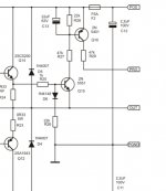
Long Time ago I find this circuit in diyuadio
Quais CLASS H Stable for BJT
I never this this circuit, and cant find more information.
I want add CLASS H to ACRTK amp for improve efficiency.
could this work any ideas ?
Im worry, long time ago nothings come from QUASI member anymore,
I thinkk its time for Final Design ACRTK with Class H and short ciruit protect.
Attachments
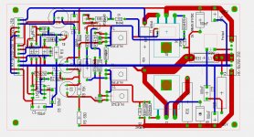
1. ACRTK redesign not tested
remove Original Quais discrete input stage and replace with
LM 318 OP input stage, (add from BGW 750B PA Amp)
2. Differential Input Board for ACRTK with NSL 32 Input and Clip Limiter
and LED for Power - Signal - CLIP
thx to APEX audio
any comments welcome
remove Original Quais discrete input stage and replace with
LM 318 OP input stage, (add from BGW 750B PA Amp)
2. Differential Input Board for ACRTK with NSL 32 Input and Clip Limiter
and LED for Power - Signal - CLIP
thx to APEX audio
any comments welcome
Attachments
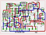
with IXYS IXTK.... Linear Mosfets amp can deliver with 1 Pair up to 1000 W @ 4 Ohm
If have time will try to add Class TD from from apex and will try it work or not
Long time ago Quasi member make this reliable design, but long time nothings new come out
Protection Board and Triac crowbar is separete
If have time will try to add Class TD from from apex and will try it work or not
Long time ago Quasi member make this reliable design, but long time nothings new come out
Protection Board and Triac crowbar is separete
Last edited:
- Status
- This old topic is closed. If you want to reopen this topic, contact a moderator using the "Report Post" button.
- Home
- Amplifiers
- Solid State
- Another quasi-complementary design